Dashboard Instrument Cluster Diagram
Every modern vehicle boasts a complex network of electrical systems, and the dashboard instrument cluster diagram is your roadmap to understanding and troubleshooting one of its most vital areas. Whether you're diagnosing a faulty gauge, planning a custom modification, or simply expanding your automotive knowledge, this diagram is an indispensable tool. We're going to dissect the intricacies of this diagram, arming you with the knowledge to confidently navigate its intricacies.
Purpose of the Instrument Cluster Diagram
Why bother with this diagram? Several compelling reasons exist:
- Diagnostics and Repair: The primary purpose is to facilitate accurate and efficient troubleshooting. When a gauge malfunctions, a warning light illuminates inexplicably, or the entire cluster goes dark, the diagram helps you pinpoint the source of the problem – whether it's a faulty sensor, a wiring issue, or a problem within the cluster itself.
- Modifications and Customization: If you're planning to upgrade your instrument cluster with aftermarket gauges, add new warning lights, or modify the lighting scheme, the diagram provides the crucial wiring information to ensure a safe and functional modification. Incorrect wiring can lead to serious electrical damage.
- Understanding Vehicle Systems: Even without immediate repair needs, studying the diagram provides valuable insight into how your vehicle's various systems interact. You gain a better understanding of how sensor signals are processed and displayed.
- Preventative Maintenance: Familiarity with the diagram enables you to proactively identify potential issues before they escalate into major problems. For example, you can check the condition of wiring connectors or identify sensors that are prone to failure.
Key Specs and Main Parts Depicted
A typical instrument cluster diagram will include several key specs and parts. These are essential for understanding the diagram and for troubleshooting. Here's a rundown:
Key Specifications
- Voltage: Usually specified as 12V (for standard automotive systems). This indicates the voltage level at which the circuit operates.
- Current Ratings: Some components, like fuses and relays, will have current ratings indicated. This is the maximum current that the component can safely handle.
- Wire Gauge (AWG): The American Wire Gauge (AWG) specifies the thickness of the wires. Thicker wires can carry more current. The diagram will indicate the AWG for different circuits.
- Connector Pinouts: Essential for identifying the function of each pin in the connectors that connect the instrument cluster to the vehicle's wiring harness.
Main Parts Shown
- Instrument Cluster Module: The central processing unit of the instrument cluster. It receives signals from various sensors and controls the gauges, warning lights, and display.
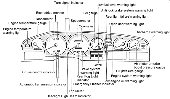
- Gauges: Speedometer, tachometer, fuel gauge, temperature gauge, oil pressure gauge, and voltmeter. The diagram will show how these gauges are wired to the instrument cluster module and their respective sensors.
- Warning Lights (Indicators): Check engine light, ABS warning light, airbag warning light, oil pressure warning light, battery warning light, and various other indicator lights. The diagram shows the wiring to these lights and the conditions under which they illuminate.
- Sensors: Speed sensor, crankshaft position sensor, coolant temperature sensor, fuel level sensor, oil pressure sensor, and other sensors that provide input to the instrument cluster.
- Wiring Harness: The bundle of wires that connects the instrument cluster to the vehicle's electrical system. The diagram shows the routing of the wires and their connections to various components.
- Connectors: The plugs that connect the wiring harness to the instrument cluster and other components. The diagram shows the pinout of each connector.
- Fuses and Relays: Fuses protect the circuits from overcurrent, and relays are used to switch high-current circuits. The diagram shows the location of fuses and relays related to the instrument cluster.
Symbols and Conventions
Instrument cluster diagrams use standardized symbols and conventions to represent electrical components and connections. Understanding these symbols is crucial for interpreting the diagram accurately.
Lines
- Solid Lines: Represent wires or conductors.
- Dashed Lines: May represent shielded wires or wires within a harness that are not individually labeled.
- Arrows: Indicate the direction of current flow.
- Line Thickness: Sometimes indicates the gauge (thickness) of the wire. Thicker lines generally represent wires carrying more current.
Colors
Wire colors are crucial for identification. Common colors and their typical functions include:
- Red: Often used for power supply (12V).
- Black: Typically used for ground.
- Yellow: Often used for switched power or signal wires.
- Blue: Often used for signal wires.
- Green: Often used for signal wires, particularly related to sensors.
- White: Can be used for various functions.
Icons
Standardized icons represent electrical components:
- Resistor: A zigzag line.
- Capacitor: Two parallel lines.
- Diode: A triangle pointing to a vertical line.
- Transistor: Various symbols depending on the type of transistor (BJT, MOSFET).
- Fuse: A zigzag line enclosed in a rectangle.
- Relay: A coil symbol connected to a switch.
- Ground: Three horizontal lines decreasing in length.
- Connector: A rectangular box with pins.
How It Works: From Sensor to Display
The instrument cluster is essentially a sophisticated data display system. It receives information from various sensors throughout the vehicle, processes that information, and then displays it to the driver.
- Sensor Input: Sensors measure various parameters, such as vehicle speed, engine speed (RPM), coolant temperature, fuel level, and oil pressure. Each sensor generates an electrical signal (voltage or current) that corresponds to the measured value.
- Signal Processing: The instrument cluster module receives these sensor signals and converts them into digital data. This involves signal conditioning, filtering, and calibration.
- Data Conversion: The digital data is then used to drive the gauges and warning lights. For gauges, the data is converted into an analog signal that controls the position of the gauge needle. For warning lights, the data is compared to threshold values, and the light is illuminated if the threshold is exceeded.
- Display Output: The gauges display the real-time values of the measured parameters, and the warning lights alert the driver to potential problems. The instrument cluster module also controls the illumination of the gauges and warning lights.
Real-World Use: Basic Troubleshooting Tips
Here are a few basic troubleshooting tips, leveraging the instrument cluster diagram:
- Gauge Malfunction: If a gauge is not working, check the wiring connections between the sensor and the instrument cluster. Use the diagram to identify the correct wires and connectors. Also, test the sensor itself to ensure that it is functioning properly. If the wiring and sensor are good, the problem may be with the instrument cluster module itself.
- Warning Light Illumination: If a warning light is illuminated, use a scan tool to read the diagnostic trouble code (DTC). The DTC will provide information about the specific problem that is causing the light to illuminate. Use the diagram to trace the circuit related to the warning light and identify potential causes.
- Cluster Completely Dead: Check the fuses and relays that power the instrument cluster. Use the diagram to identify the correct fuses and relays. If the fuses are good, check the wiring connections to the instrument cluster.
- Intermittent Problems: Intermittent problems can be difficult to diagnose. Carefully inspect the wiring harness for any signs of damage, such as frayed wires, corroded connectors, or loose connections. Use the diagram to identify potential areas of concern.
Always remember to disconnect the negative battery terminal before working on any electrical components.
Safety Precautions
Working with automotive electrical systems can be dangerous. Be aware of the following:
- Airbag System: The instrument cluster is often connected to the airbag system. Never disconnect or tamper with the airbag system unless you are a qualified technician. Improper handling of the airbag system can result in accidental deployment, causing serious injury.
- High Voltage: While most circuits are 12V, some components, like the ignition system, can carry high voltage. Avoid contact with these components.
- Short Circuits: Avoid creating short circuits, as they can damage electrical components and start fires. Always disconnect the negative battery terminal before working on electrical components.
- Tools: Use insulated tools to prevent electrical shock.
We have a detailed instrument cluster diagram available for download. This diagram provides comprehensive wiring information and component locations, making it an invaluable resource for troubleshooting and repair. You can download the diagram here (link to diagram). This detailed information will empower you to tackle instrument cluster issues with confidence and precision.