
Delco 4 Wire Alternator Wiring Diagram
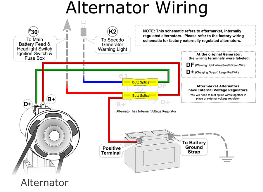
Alright, let's dive into the often-misunderstood world of Delco 4-wire alternator wiring diagrams. Whether you're upgrading your classic car, troubleshooting charging issues, or simply expanding your automotive knowledge, understanding this setup is crucial. This article will walk you through the specifics, offering clear explanations and practical advice.
Purpose of Understanding the Delco 4-Wire Alternator Wiring Diagram
Why bother learning about this wiring diagram? Several reasons: first and foremost is troubleshooting charging problems. A faulty connection or wiring issue within the alternator circuit can lead to a dead battery, poor performance, and frustrating breakdowns. Secondly, retrofitting. Many older vehicles didn't use internally regulated alternators. Upgrading to a modern Delco 4-wire unit improves charging efficiency and reliability. Finally, custom builds and modifications. If you're building a custom car or modifying an existing one, understanding the wiring is essential for proper integration of the alternator into the vehicle's electrical system.
Key Specs and Main Parts
Before we get into the diagram itself, let's define the key components we'll be dealing with:
- Alternator: The heart of the charging system, converting mechanical energy from the engine into electrical energy to charge the battery and power the vehicle's electrical components.
- Voltage Regulator: Integrated inside the Delco alternator. It maintains a stable output voltage (typically around 13.8-14.4 volts) regardless of engine speed and electrical load. Without it, the alternator could overcharge the battery and damage electrical components.
- Battery: Stores electrical energy and provides power to start the engine and operate electrical components when the engine isn't running.
- Ignition Switch: Controls the flow of power to various circuits in the vehicle, including the alternator's field circuit.
- Fusible Link/Fuse: A safety device designed to protect the wiring and components from excessive current flow. Think of it as a circuit breaker.
The "4 wires" in the name refer to the four key connections on the alternator:
- Battery (B+) Terminal: This is the heavy-gauge wire that connects directly to the positive terminal of the battery (or a remote junction point connected to the battery). It carries the main charging current.
- Sense Wire (Terminal #2 or "Voltage Sense"): This wire monitors the voltage at a remote point in the electrical system (usually near the battery or at the fuse box). It allows the voltage regulator to compensate for voltage drop in the wiring, ensuring that the battery receives the correct charging voltage.
- Exciter Wire (Terminal #1 or "Ignition"): This wire provides a small amount of current from the ignition switch to "excite" the alternator's field windings, initiating the charging process. Without this signal, the alternator won't start charging.
- Ground: The alternator case must be properly grounded to the engine block (and subsequently the vehicle's chassis) to complete the electrical circuit. A dedicated ground wire is often used, although sometimes the mounting bracket provides sufficient ground.
Understanding the Symbols in the Diagram
A wiring diagram is essentially a map of the electrical system. Here's a breakdown of common symbols you'll encounter:
- Solid Lines: Represent wires. The thickness of the line *may* indicate the wire gauge (thicker lines for higher current-carrying capacity), but this isn't always consistent.
- Dotted Lines: Often indicate ground connections or wires located inside a wiring harness.
- Circles: Can represent various components, such as connectors, fuses, or light bulbs. A circle with an "X" through it typically represents a light bulb.
- Rectangles: Usually represent switches, relays, or other electronic modules.
- Ground Symbol: A series of horizontal lines decreasing in length, indicating a connection to ground (the vehicle's chassis).
Color Coding: Wire colors are crucial for identification. Common colors include red (positive voltage), black (ground), and various other colors (e.g., blue, green, yellow) for specific circuits. The diagram will usually have a legend explaining the color coding.
Abbreviations: Pay attention to abbreviations such as B+ (Battery positive), IGN (Ignition), and GND (Ground).
How the Delco 4-Wire Alternator Works
Here's the process in a nutshell:
- When you turn the ignition key to the "on" position, the exciter wire (Terminal #1) receives power from the ignition switch.
- This small current flows through the alternator's field windings, creating a magnetic field.
- As the engine starts and the alternator begins to spin, this magnetic field induces a voltage in the stator windings.
- This voltage is rectified (converted from AC to DC) by diodes inside the alternator.
- The voltage regulator monitors the voltage at the sense wire (Terminal #2).
- Based on the voltage sensed, the regulator adjusts the current flowing through the field windings, controlling the alternator's output voltage.
- The regulated voltage is then supplied to the battery (via the B+ terminal) to charge it and power the vehicle's electrical system.
Real-World Use: Basic Troubleshooting
Let's say you suspect a charging problem. Here's how the wiring diagram can help:
- No Charging: Use a multimeter to check for voltage at the B+ terminal with the engine running. If there's no voltage (or significantly low voltage), check the fuse or fusible link in the B+ circuit. Also verify a good ground connection. Then check for voltage at Terminal 1 with the ignition ON. No voltage means a problem in the ignition circuit.
- Overcharging: This is usually a faulty voltage regulator *inside* the alternator. Replace the alternator. However, double check the sense wire. If it’s disconnected or corroded, it may be sending a low-voltage signal, causing the regulator to compensate.
- Battery Draining: A faulty diode in the alternator can cause a parasitic draw, draining the battery even when the engine is off. Disconnect the alternator and see if the drain stops.
Important: Always use a multimeter to check for voltage and continuity. Visual inspection alone is often insufficient.
Safety First!
Working with automotive electrical systems can be dangerous. Here are some key safety precautions:
- Disconnect the Battery: Always disconnect the negative battery terminal before working on any electrical components. This prevents accidental short circuits.
- High Current: The B+ terminal and its wiring carry high currents. Avoid touching these wires while the engine is running or the battery is connected.
- Proper Tools: Use insulated tools to prevent electrical shock.
- Fuses: Never replace a fuse with one of a higher amperage rating. This can overload the circuit and cause a fire.
- Work Area: Work in a well-lit and ventilated area.
Note on Capacitors: Some aftermarket audio systems include large capacitors. These can store a significant amount of energy even after the battery is disconnected. Discharge these capacitors before working on the electrical system.
By understanding the Delco 4-wire alternator wiring diagram, you'll be better equipped to diagnose and repair charging system problems, perform upgrades, and build custom automotive projects with confidence. Always double check your connections and take the necessary safety precautions.