Delco Chevy 4 Wire Alternator Wiring Diagram
The Delco Remy 4-wire alternator, particularly common in older Chevy vehicles (but adaptable to many others), is a robust and reliable charging system component. Understanding its wiring is crucial for a variety of reasons: diagnosing charging problems, performing repairs, swapping out a faulty unit, or even upgrading your classic ride. This guide provides a comprehensive breakdown of the Delco Chevy 4-wire alternator wiring diagram, aimed at intermediate car owners and DIY mechanics.
Purpose of Understanding the Wiring Diagram
Why delve into the intricacies of this wiring? There are several compelling reasons:
- Troubleshooting Charging Issues: When your battery isn't charging, the alternator is often the prime suspect. The wiring diagram allows you to systematically check connections, identify shorts, and confirm proper signal flow.
- Alternator Replacement: Swapping an alternator is a relatively straightforward job, but proper wiring is essential to avoid damaging the new unit or the vehicle's electrical system.
- Custom Wiring/Modifications: If you're building a custom vehicle, performing an engine swap, or upgrading your electrical system, understanding how to integrate the Delco 4-wire alternator is vital.
- Learning Automotive Electrical Fundamentals: The Delco 4-wire alternator is a relatively simple system, making it an excellent learning tool for understanding basic automotive electrical principles.
Key Specs and Main Parts
Let's begin by identifying the key components and their specifications:
- Alternator Housing: The physical enclosure containing the rotor, stator, rectifier bridge, and voltage regulator.
- Rotor: The rotating electromagnetic component, driven by the engine's accessory belt. It generates a magnetic field when energized.
- Stator: A set of stationary windings that surround the rotor. The rotating magnetic field induces an AC voltage in the stator windings.
- Rectifier Bridge: A set of diodes that convert the AC voltage from the stator into DC voltage, which is required by the vehicle's electrical system. Think of it as a one-way valve for electricity.
- Voltage Regulator: A crucial component that maintains a constant output voltage (typically around 13.8-14.5 volts) regardless of engine speed or electrical load. This prevents overcharging the battery and damaging electrical components.
- 4-Wire Connector: The focus of our discussion. These four wires are:
- Battery (BAT) Terminal: A heavy-gauge wire that connects directly to the battery positive (+) terminal or a junction point that feeds the battery. It carries the main charging current.
- Remote Voltage Sensing (S) Terminal: A smaller-gauge wire that connects to a point in the electrical system where you want to monitor the voltage (typically near the battery or the fuse box). The voltage regulator uses this signal to compensate for voltage drops in the wiring.
- Ignition (IGN) Terminal: Also known as the exciter wire. It receives power from the ignition switch when the key is in the "run" position. This provides the initial current to energize the rotor and start the charging process.
- Ground (GND) Terminal: Connects the alternator housing to the vehicle's chassis ground. A good ground connection is essential for proper operation.
Symbols and Diagram Conventions
Understanding the symbols used in the wiring diagram is essential for interpreting it correctly:
- Solid Lines: Represent wires. The thickness of the line usually corresponds to the wire gauge (thicker lines indicate larger gauge wires carrying more current).
- Dotted Lines: May represent wires hidden behind other components or wires that are part of an internal circuit within the alternator.
- Colors: Wire colors are usually indicated on the diagram using abbreviations (e.g., RED, BLU, GRN, BLK). The color coding helps you identify the correct wires in the vehicle's wiring harness.
- Symbols for Components:
- Alternator: Usually depicted as a circle with a symbol representing the rotor and stator windings.
- Battery: Represented by a series of short and long parallel lines (the longer line indicates the positive terminal).
- Fuse: Shown as a zigzag line inside a rectangle or a simple line break with a numerical value (indicating the fuse amperage rating).
- Ground: Typically shown as a series of downward-pointing horizontal lines (resembling an inverted pyramid).
- Ignition Switch: Represented as a switch symbol with different positions (e.g., OFF, ACC, RUN, START).
- Numerical Values: May indicate wire gauge (e.g., 10 AWG), fuse amperage rating (e.g., 20A), or voltage levels (e.g., 12V).
How It Works: A Simplified Explanation
Here's how the Delco 4-wire alternator charging system operates:
- Ignition On: When you turn the ignition key to the "run" position, power is supplied to the IGN terminal of the alternator. This small current flows through the rotor windings, creating an initial magnetic field.
- Engine Starts: As the engine starts, the accessory belt drives the alternator's rotor. The rotating magnetic field induces an AC voltage in the stator windings.
- Rectification: The rectifier bridge converts the AC voltage from the stator into DC voltage.
- Voltage Regulation: The voltage regulator monitors the system voltage via the remote voltage sensing (S) terminal. If the voltage is too low, the regulator increases the current flowing through the rotor windings, strengthening the magnetic field and increasing the output voltage. If the voltage is too high, the regulator reduces the rotor current.
- Charging the Battery: The DC voltage from the alternator is then supplied to the battery through the BAT terminal, charging the battery and powering the vehicle's electrical system.
Real-World Use: Basic Troubleshooting Tips
Here are some basic troubleshooting tips using the wiring diagram:
- No Charging:
- Check the IGN wire: Is it receiving power when the ignition is on? Use a multimeter to verify voltage.
- Check the BAT wire: Is it properly connected to the battery (or a junction point leading to the battery)? Inspect for corrosion or loose connections. Use a multimeter to check for voltage at the alternator BAT terminal when the engine is running. It should be close to battery voltage.
- Check the S wire: Ensure the S wire is connected to a good sensing point (near the battery or fuse box). Disconnecting it will usually cause the alternator to output at the high end.
- Check the Ground wire: Ensure a solid connection between the alternator housing and the vehicle's chassis ground. A bad ground can cause all sorts of charging problems. Clean the contact points to ensure a good connection.
- Fuse Check: Inspect the fuse in the IGN circuit. A blown fuse will prevent the alternator from starting to charge.
- Overcharging:
- Voltage Regulator: A faulty voltage regulator is the most common cause of overcharging. It needs to be replaced.
- S wire: Check for proper connection and wire integrity of the S wire. A faulty S wire can cause the alternator to overcharge, because it is not reading an accurate measurement.
Safety Precautions
Working on automotive electrical systems can be dangerous. Observe these safety precautions:
- Disconnect the Battery: Always disconnect the negative (-) battery terminal before working on any electrical components. This prevents accidental shorts and potential damage to the electrical system.
- Be Mindful of High Current: The BAT wire carries a significant amount of current. Avoid shorting it to ground, as this can cause sparks, fires, and damage to the wiring harness.
- Avoid Touching Moving Parts: When the engine is running, be careful to avoid touching the alternator's rotating components (pulley, fan).
- Wear Safety Glasses: Protect your eyes from sparks and debris.
- Use Proper Tools: Use insulated tools to prevent electrical shock.
Warning: The battery and the alternator's BAT terminal are high-current sources. Shorting these components can result in severe burns, electrical shock, and vehicle damage. Always disconnect the battery negative cable before working on the electrical system.
Important Note: Replacing an alternator doesn't guarantee a fix. Always diagnose the underlying problem before replacing parts. A faulty wiring connection, a bad battery, or a parasitic drain can all cause charging system issues.
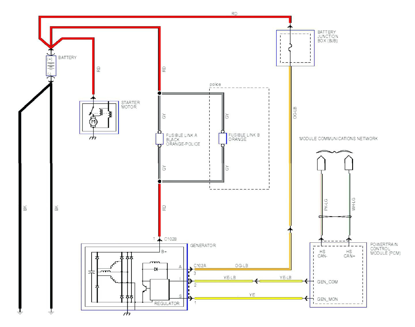
We have a detailed, downloadable Delco Chevy 4-wire alternator wiring diagram available for your use. This diagram will provide a visual representation of the wiring connections and component locations, making it easier to troubleshoot and repair your charging system.