Delco Remy 3 Wire Alternator Wiring Diagram
The Delco Remy 3-wire alternator wiring diagram is your roadmap to understanding, troubleshooting, and potentially modifying a very common charging system found on countless vehicles, particularly older American models. Whether you're wrestling with a dimming headlight, planning an engine swap, or simply expanding your automotive electrical knowledge, mastering this diagram is invaluable. We have the wiring diagram available for download; simply reference the link provided at the end of this article.
Purpose of Understanding the 3-Wire Alternator Wiring Diagram
This diagram isn't just a pretty picture; it's a crucial tool for several reasons:
- Troubleshooting Charging Issues: Diagnose problems like a dead battery, undercharging, or overcharging. It helps pinpoint whether the alternator, wiring, or other components are at fault.
- Engine Swaps and Modifications: Integrate a Delco Remy 3-wire alternator into a non-original vehicle or electrical system. This ensures proper charging functionality and prevents electrical nightmares.
- System Upgrades: Understand how to upgrade your charging system for increased amperage, often required for vehicles with high electrical demands (e.g., aftermarket audio systems, winches, off-road lighting).
- Learning Automotive Electrical Systems: Gain a deeper understanding of how alternators, voltage regulators, and the rest of the charging system interact. This knowledge is broadly applicable to all automotive electrical work.
Key Specs and Main Parts
Before diving into the diagram, let's establish some key specifications and component descriptions:
- Delco Remy Alternator: A specific brand and style of alternator known for its durability and widespread use. There are many different output amperage ratings, make sure your alternator is appropriate for the vehicle.
- 3-Wire Configuration: This distinguishes it from 1-wire alternators. The 3 wires provide specific functions as detailed below.
- Voltage Regulator: Controls the alternator's output voltage to prevent overcharging and protect the battery and electrical components. This regulator is usually internal in modern alternators, but can be external for older models.
- Battery: The heart of the electrical system, providing starting power and storing energy from the alternator.
- Wiring Gauge: The thickness of the wires is crucial for carrying the necessary current without overheating. Using the correct gauge is critical for safety and performance.
- Amperage Rating: The maximum current the alternator can produce (e.g., 63 amps, 100 amps).
- Voltage: Typically 12 volts in most automotive applications.
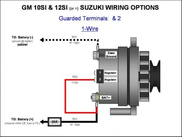
The Three Wires:
- Battery Terminal (BAT or Large Post): This thick wire connects directly to the positive (+) terminal of the battery or to the starter solenoid where the battery cable is connected. It carries the main charging current from the alternator to the battery and the rest of the vehicle's electrical system.
- Sense Wire (Usually Smaller Gauge Red Wire): This wire provides a voltage reference to the voltage regulator. The regulator uses this signal to determine the battery's voltage and adjust the alternator's output accordingly. Connecting it to a point *farther away* from the battery (but still on a +12V circuit) provides voltage drop compensation for long wire runs or high current loads.
- Exciter Wire (Often a Smaller Gauge Brown or Blue Wire): This wire provides a small initial current to excite the alternator's field windings during startup. It is usually connected to the ignition switch so that the alternator only charges when the engine is running. This prevents the alternator from draining the battery when the engine is off.
Understanding the Diagram Symbols
A wiring diagram uses standardized symbols to represent electrical components and connections. Here's a breakdown:
- Solid Lines: Represent wires. The thickness of the line might indicate the wire gauge.
- Dashed Lines: Sometimes used to represent grounds, or less critical connections.
- Colors: Wires are often color-coded (e.g., Red for positive, Black for ground). These colors are noted on the diagram.
- Circles: Can represent connections or components.
- Rectangles: Often used for relays, voltage regulators, or other control modules.
- Ground Symbol (Three Horizontal Lines): Indicates a connection to the vehicle's chassis, providing a return path for the current.
- Battery Symbol: A series of alternating long and short lines (+ and -).
- Alternator Symbol: Varies but usually depicts a rotating component with terminals.
How the 3-Wire Alternator System Works
The 3-wire Delco Remy alternator system works on the principle of electromagnetic induction. Here's the basic process:
- Ignition On: When the ignition switch is turned on, the exciter wire receives power. This small current energizes the field windings within the alternator.
- Engine Starts: As the engine starts and the alternator begins to rotate, the spinning rotor (driven by the engine's belt) generates an alternating current (AC) in the stator windings.
- Rectification: The AC current is converted to direct current (DC) by a set of diodes within the alternator.
- Voltage Regulation: The voltage regulator monitors the voltage at the sense wire. It compares this voltage to a preset value (typically around 14.2 volts). If the voltage is too low, the regulator increases the current flowing through the field windings, increasing the alternator's output. If the voltage is too high, it reduces the field current.
- Charging the Battery: The DC current from the alternator flows through the battery terminal wire to the battery, replenishing its charge. It also powers the rest of the vehicle's electrical system.
The sense wire is crucial because it provides feedback to the regulator. Without it, or if it's improperly connected, the regulator won't be able to accurately control the alternator's output, potentially leading to overcharging or undercharging.
Real-World Use: Basic Troubleshooting Tips
Here are a few troubleshooting tips using the 3-wire alternator wiring diagram:
- No Charging: Check the exciter wire for power when the ignition is on. If there's no power, trace the wire back to the ignition switch or any related fuses. Use a multimeter to verify voltage.
- Overcharging: A common cause is a faulty voltage regulator or a bad connection on the sense wire. Check the sense wire connection and replace the regulator if necessary. Overcharging can boil the battery and damage electrical components.
- Undercharging: Could be a faulty alternator, a slipping belt, or a bad battery. Test the alternator's output voltage with a multimeter. Verify the belt is tight and in good condition. Have the battery load-tested.
- Dim Lights: This can indicate a weak alternator or a problem with the charging system. Check the alternator's output voltage under load (e.g., with headlights and accessories on). Also check the ground connections.
- Battery Light On: Usually indicates a problem with the charging system. Use the diagram to isolate the issue.
Remember to always use a multimeter to verify voltage and continuity. Continuity is the presence of a complete circuit path.
Safety Precautions
Working with automotive electrical systems can be dangerous. Always take these precautions:
- Disconnect the Battery: Before working on any electrical components, disconnect the negative (-) battery cable. This prevents accidental shorts and electrical shocks.
- Wear Safety Glasses: Protect your eyes from sparks and debris.
- Use Insulated Tools: Prevent electrical shocks by using tools with insulated handles.
- Work in a Well-Ventilated Area: Batteries can produce explosive hydrogen gas.
- Be Careful Around the Alternator Pulley: The alternator pulley spins at high speeds when the engine is running. Keep your hands and tools clear of the pulley.
- High current flowing through the thick battery cable can cause severe burns if shorted to ground. Exercise extreme caution when working with this cable.
Remember that the alternator can output significant voltage and amperage. Avoid touching any exposed terminals or wires while the engine is running.
Where to Get the Diagram
Now that you understand the fundamentals, you'll need the actual wiring diagram to work on your vehicle. We have a downloadable version of the Delco Remy 3-wire alternator wiring diagram available. Look for the download link below:
[Download Link Here – Replace with Actual Link]
By understanding the diagram and following safety precautions, you can confidently diagnose and repair charging system issues, upgrade your electrical system, and expand your automotive knowledge.