Delco Remy Voltage Regulator Wiring Diagram
Understanding the wiring diagram for a Delco Remy voltage regulator is crucial for any serious DIY mechanic or car enthusiast working on older vehicles, particularly those from the mid-20th century through the 1980s. These diagrams provide a roadmap to a critical component in your car's electrical system, allowing for informed troubleshooting, repair, and even modification. Without it, you're essentially operating blind, guessing at connections and risking damage to components. We will explore the ins and outs of these diagrams, making you better equipped to handle your vintage vehicle's electrical needs.
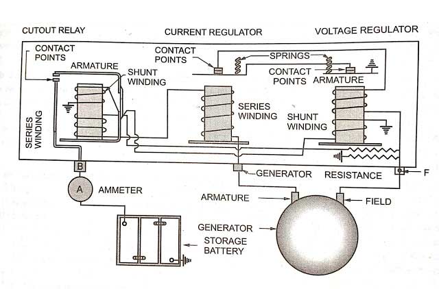
Purpose of Delco Remy Voltage Regulator Wiring Diagram
The primary purpose of a Delco Remy voltage regulator wiring diagram is threefold:
- Repair: When your charging system isn't behaving, the diagram is your go-to resource for tracing faults. You can check wire continuity, identify broken connections, and confirm that everything is wired correctly.
- Understanding: The diagram provides a visual representation of the regulator's internal workings and its relationship to other components, such as the alternator, battery, and ignition switch. This knowledge allows for a deeper understanding of the overall charging system.
- Modification: Whether you're upgrading to a higher-output alternator or converting to a different type of charging system, the wiring diagram is essential for ensuring proper integration and avoiding electrical mishaps.
Key Specs and Main Parts of Voltage Regulator
Before diving into the diagram itself, it's important to understand the key specs and main parts involved. Delco Remy regulators are typically electromechanical, meaning they use mechanical relays and electromagnets to control the alternator's output. These regulators maintain a stable voltage output (typically around 13.8-14.5 volts) to charge the battery and power the vehicle's electrical accessories.
The main parts usually represented in the diagram are:
- Battery (BAT) Terminal: Connects directly to the positive terminal of the battery. This is the source of power for the regulator.
- Field (FLD) Terminal: Connects to the alternator's field winding (rotor). The regulator controls the current flow through this winding, which determines the alternator's output.
- Armature (ARM) or Generator (GEN) Terminal: Connects to the alternator's output terminal (stator). It senses the alternator's voltage output.
- Ground (GND) Terminal: Connects to the vehicle's chassis ground.
- Voltage Regulator Relay: This relay controls the voltage output. When the voltage is too low, the relay closes, allowing more current to flow to the field winding.
- Current Regulator Relay: This relay limits the charging current to protect the alternator from overload.
- Resistors and Diodes: These components are used to control current flow and provide voltage drops within the regulator.
Symbols in the Wiring Diagram
Delco Remy wiring diagrams employ a standardized set of symbols to represent various components and connections. Understanding these symbols is critical to interpreting the diagram correctly.
- Lines: Solid lines represent wires. Dashed lines may indicate a connection to ground or a shielded wire. The thickness of a line doesn't necessarily indicate wire gauge in all diagrams, but in some schematics it can be used to denote wire size (thicker lines = larger gauge).
- Colors: Wire colors are often indicated next to the lines (e.g., "RED," "BLK," "BLU"). These colors are standardized and can help you identify the correct wires in the vehicle.
- Circles: Often indicate terminals or connection points.
- Rectangles: May represent components such as relays, resistors, or diodes.
- Ground Symbol: A downward-pointing triangle or a series of horizontal lines indicates a connection to ground.
- Battery Symbol: Represents the battery, with "+" and "-" signs indicating the positive and negative terminals, respectively.
- Relay Symbol: A coil with a switch mechanism indicates a relay. The diagram shows how the coil, when energized, causes the switch to change position.
- Resistor Symbol: A zigzag line represents a resistor.
- Diode Symbol: A triangle pointing to a vertical line represents a diode. It allows current to flow in only one direction.
How It Works – The Charging System in Brief
The Delco Remy regulator works by controlling the current flowing through the alternator's field winding. Here’s a simplified overview:
- When the engine starts, the alternator begins to spin, generating voltage.
- The regulator monitors the voltage at the ARM terminal.
- If the voltage is below the setpoint (e.g., 13.8 volts), the voltage regulator relay closes, allowing more current to flow to the field winding. This increases the alternator's output.
- As the voltage rises, the regulator progressively reduces the current to the field winding, preventing overcharging.
- The current regulator relay protects the alternator from excessive current output. If the current exceeds a certain limit, the relay reduces the current to the field winding.
Real-World Use – Basic Troubleshooting Tips
Here are some basic troubleshooting tips using the wiring diagram:
- No Charging: If the battery isn't charging, check the voltage at the BAT terminal of the regulator. If there's no voltage, check the battery connection and the wiring between the battery and the regulator. Also verify the ground connection is solid.
- Overcharging: If the battery is overcharging (e.g., voltage above 15 volts), the regulator may be faulty. Use the diagram to check the wiring to the FLD terminal. A shorted or open circuit in this wiring can cause overcharging.
- Excessive Current: If the alternator is overheating or blowing fuses, the current regulator relay may be malfunctioning. Use the diagram to check the wiring and connections associated with this relay.
- Using a Multimeter: With the wiring diagram, you can use a multimeter to check for voltage drops across wires, confirm continuity, and verify that relays are functioning correctly. Remember to disconnect the battery's negative terminal before working on the electrical system.
When troubleshooting, systematically check each connection and component identified in the wiring diagram. A visual inspection can often reveal obvious problems like broken wires, corroded terminals, or damaged components.
Safety Considerations
Working with electrical systems can be dangerous. Here are some safety precautions to keep in mind:
- Disconnect the Battery: Always disconnect the negative terminal of the battery before working on the electrical system. This prevents accidental shorts and electrical shocks.
- Be Careful with Live Wires: Avoid touching exposed wires or terminals while the engine is running or the ignition is on.
- Use Insulated Tools: Use tools with insulated handles to prevent electrical shocks.
- Beware of Capacitors: Some regulators contain capacitors that can store a charge even after the battery is disconnected. Discharge these capacitors before working on the regulator. A resistor can be used for this purpose.
The alternator itself, particularly the rectifier diodes inside, can fail in a way that creates a short circuit. This can cause the alternator to get extremely hot very quickly and even pose a fire hazard. If you suspect a shorted diode, replace the alternator.
Disclaimer: This information is provided for educational purposes only and should not be considered a substitute for professional automotive advice. Always consult with a qualified mechanic if you are unsure about any aspect of your vehicle's electrical system.
With this knowledge and a Delco Remy voltage regulator wiring diagram in hand, you're well-equipped to diagnose and repair charging system issues on your vintage vehicle. Remember to work safely and methodically, and you'll be back on the road in no time.
We have a variety of Delco Remy voltage regulator wiring diagrams available for download. Please [link to download page or contact form] to access the file applicable to your specific vehicle model and year. Be sure to specify the make, model, and year of your vehicle for us to provide the most accurate diagram.