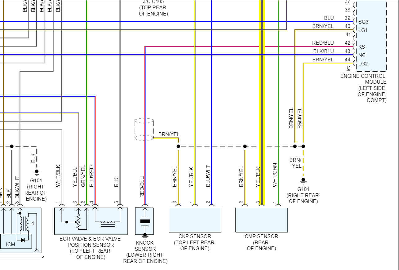
Diagram 3 Wire Camshaft Position Sensor Wiring Harness
Understanding your car's electrical system can seem daunting, but with a clear grasp of wiring diagrams, even complex components become manageable. Today, we'll dissect the wiring diagram for a 3-wire Camshaft Position (CMP) sensor. This isn't just about fixing a broken wire; it’s about gaining a deeper insight into how your engine management system functions, enabling more effective diagnostics and repairs.
Purpose of Understanding the CMP Wiring Diagram
Why bother with a diagram? Well, having a solid understanding of your CMP sensor wiring allows you to:
- Troubleshoot sensor malfunctions: Identify broken wires, shorts to ground, or open circuits.
- Confirm proper sensor voltage: Ensure the sensor is receiving the correct power supply and ground.
- Learn how the ECM interacts with the sensor: Understanding the signals being sent and received provides insight into the engine's operation.
- Perform custom modifications: If you're undertaking engine modifications, understanding the CMP signal is critical for correct timing and fuel delivery.
Key Specifications and Main Parts of a 3-Wire CMP Sensor System
A 3-wire CMP sensor system is relatively straightforward, comprising the following key parts:
- The CMP Sensor Itself: This is the core component. It detects the position of the camshaft, sending a signal to the ECM.
- The Wiring Harness: The bundle of wires connecting the sensor to the engine control module (ECM).
- The Engine Control Module (ECM): The "brain" of the engine. It processes the CMP sensor's signal to control ignition timing and fuel injection.
The 3 wires are typically:
- Power Wire (VCC or +5V): Provides a constant voltage supply to the sensor, often 5 volts DC. This is usually supplied by the ECM.
- Ground Wire (GND): Provides a return path for the current, ensuring a complete circuit. Also connected to the ECM.
- Signal Wire (SIG): Carries the signal from the sensor to the ECM, indicating the camshaft's position. The signal is often a PWM (Pulse Width Modulation) or a digital square wave.
Key Specs to Consider:
- Voltage: The power wire typically carries 5 volts. Checking this voltage with a multimeter is a fundamental troubleshooting step.
- Resistance: While not directly applicable to the wiring itself, understanding the sensor's internal resistance can be helpful in advanced diagnostics.
- Waveform: The signal wire carries a specific waveform. Analyzing this waveform with an oscilloscope can reveal sensor malfunctions.
Understanding Wiring Diagram Symbols
Deciphering a wiring diagram relies on understanding its symbols. Here's a breakdown of what you'll typically encounter:
- Lines: Wires are represented by lines. Thicker lines might indicate wires carrying higher current.
- Colors: Each wire has a specific color code (e.g., RED, BLU, GRN). These colors are crucial for identifying the correct wires in the harness. Common abbreviations include:
- BLK: Black
- RED: Red
- GRN: Green
- BLU: Blue
- WHT: White
- YEL: Yellow
- Connectors: Represented by squares, circles, or other shapes, indicating points where wires are connected or disconnected.
- Ground Symbols: Represented by a series of descending horizontal lines, showing the ground connection.
- Component Symbols: Each component has a unique symbol. The CMP sensor might be depicted as a circle with a sine wave inside, or a more detailed representation of its internal circuitry. The ECM will usually be represented as a box with numbered or lettered pins.
The wiring diagram will show you the physical connection points between the CMP sensor, the ECM, and the ground. It will also denote the color of each wire in the harness, making it much easier to identify the correct wire to test or repair.
How the 3-Wire CMP Sensor System Works
The 3-wire CMP sensor is usually a Hall-effect sensor. A Hall-effect sensor works by detecting changes in a magnetic field. A rotating toothed wheel, or reluctor ring, is attached to the camshaft. As the camshaft rotates, the teeth of the reluctor ring pass by the sensor.
Here’s the step-by-step process:
- The ECM supplies 5V (or other specified voltage) to the CMP sensor via the power wire.
- The sensor uses this voltage to power its internal circuitry.
- As the camshaft rotates, the reluctor wheel passes by the sensor.
- The sensor detects the changes in the magnetic field as the teeth of the reluctor ring pass, creating a pulsed voltage signal.
- The sensor sends a signal to the ECM through the signal wire.
- The ECM reads this signal and uses the camshaft position information to accurately time fuel injection and ignition.
The timing of the camshaft in relation to the crankshaft is critical for engine performance and efficiency.
Real-World Use: Basic Troubleshooting Tips
Let's say your car is throwing a CMP sensor code (e.g., P0340). Here’s how you can use the wiring diagram to troubleshoot:
- Visual Inspection: Start by visually inspecting the wiring harness for any obvious damage, such as frayed wires, broken connectors, or corrosion.
- Voltage Check: Use a multimeter to check the voltage at the sensor's power wire. It should read close to 5V with the ignition on. If not, there might be a problem with the ECM or the wiring to the sensor.
- Ground Check: Use a multimeter to check the ground wire for continuity to ground. There should be very little resistance (close to 0 ohms). If not, there's a problem with the ground connection.
- Signal Wire Check: With the engine running, use an oscilloscope to observe the signal waveform on the signal wire. The waveform should be a clean square wave or PWM signal. If the signal is erratic or missing, the sensor might be faulty, or there could be an issue with the wiring.
- Continuity Check: Use a multimeter to check the continuity of each wire between the sensor and the ECM. If there's no continuity, the wire is broken.
If you find a broken wire, you can use the wiring diagram to identify the correct replacement wire and properly splice it into the harness. Ensure you use appropriate crimping tools and waterproof connectors to prevent future corrosion.
Safety Considerations
Working with automotive electrical systems involves potential hazards. Here are some safety precautions:
- Disconnect the Battery: Always disconnect the negative battery terminal before working on any electrical components. This prevents accidental shorts and potential electrical shocks.
- High Voltage: Be aware that some components, such as the ignition system, can carry high voltage. Avoid touching these components while the engine is running.
- Fuel Leaks: Be extremely careful when working around fuel lines. Fuel leaks can be a fire hazard.
- Proper Tools: Use the correct tools for the job. This includes insulated screwdrivers, wire strippers, and crimping tools.
Understanding the 3-wire CMP sensor wiring diagram is a valuable skill for any DIY mechanic. It empowers you to diagnose problems, perform repairs, and even undertake custom modifications with confidence. By understanding the purpose, components, symbols, and troubleshooting techniques, you can effectively navigate the complexities of your car's electrical system.
We have a sample diagram that may be relevant to your application. If interested, you can download the diagram HERE.