Diagram Car Air Conditioning System Components
Understanding your car's air conditioning (A/C) system is crucial for maintaining comfort and potentially saving money on costly repairs. A detailed diagram of the A/C components acts as a roadmap, enabling you to diagnose issues, perform basic maintenance, and even consider modifications with confidence. This guide will walk you through the key elements of a typical automotive A/C system diagram, explaining their functions, symbols, and how they interact.
Why a Diagram Matters
An A/C system diagram is more than just a pretty picture; it's a vital tool for several reasons:
- Troubleshooting: Pinpointing the source of A/C problems becomes significantly easier when you can trace the refrigerant flow and identify each component. Is it the compressor, the expansion valve, or a dreaded leak? The diagram guides you.
- Repair and Maintenance: Whether you're replacing a faulty part or performing routine maintenance, the diagram ensures you're working on the correct component and following the correct procedures.
- Learning and Education: Familiarizing yourself with the A/C system's layout allows you to understand the overall operation, enhancing your knowledge of automotive systems.
- Modifications: Planning an upgrade to your A/C, such as adding a larger condenser or replacing a weak compressor? A diagram helps you visualize the impact of your modifications and ensures compatibility.
Key Specs and Main Parts
Before diving into the diagram's symbols, let's identify the essential components of a car A/C system:
- Compressor: The heart of the system, the compressor circulates refrigerant under pressure. It takes low-pressure, low-temperature gas and compresses it into high-pressure, high-temperature gas. Compressors are typically driven by a belt connected to the engine's crankshaft. Different types exist, including reciprocating, rotary vane, and scroll compressors. Key specs include displacement (measured in cubic centimeters or inches) and the type of refrigerant they are compatible with.
- Condenser: The condenser's job is to cool the high-pressure, high-temperature refrigerant gas and turn it into a high-pressure liquid. Located at the front of the vehicle (often in front of the radiator), it uses airflow to dissipate heat. Condenser size (surface area) and fin density affect its cooling efficiency.
- Receiver-Drier (or Accumulator): This component filters the refrigerant and removes moisture. It also acts as a temporary storage reservoir. Receiver-driers are usually found in systems that use a thermal expansion valve (TXV), while accumulators are used in systems with an orifice tube. Accumulators also have a desiccant to absorb moisture.
- Expansion Valve (or Orifice Tube): The expansion valve (TXV) or orifice tube regulates the flow of refrigerant into the evaporator. It also causes a pressure drop, which lowers the refrigerant's temperature. The TXV is a more sophisticated device that automatically adjusts the refrigerant flow based on the evaporator's temperature, while the orifice tube is a simpler, fixed-size restrictor.
- Evaporator: Located inside the vehicle's HVAC (Heating, Ventilation, and Air Conditioning) unit, the evaporator absorbs heat from the cabin air, cooling it down. As the refrigerant absorbs heat, it changes from a low-pressure liquid to a low-pressure gas.
- Refrigerant Lines (Hoses): These lines connect all the components, carrying the refrigerant throughout the system. They are designed to withstand the high pressures and temperatures involved.
- Pressure Switches: These switches monitor the refrigerant pressure and protect the system from damage. They can shut off the compressor if the pressure is too low (indicating a leak) or too high (indicating a blockage or overcharge).
- Blower Motor: While not directly part of the refrigerant cycle, the blower motor forces air across the evaporator, circulating the cooled air into the cabin.
Symbols: Understanding the Language
A/C system diagrams use standardized symbols to represent components and connections. Here's a breakdown of common symbols:
- Lines: Lines represent the refrigerant lines. Solid lines typically indicate high-pressure lines, while dashed lines represent low-pressure lines.
- Arrows: Arrows indicate the direction of refrigerant flow.
- Compressor: Often depicted as a circle with a gear or piston inside, symbolizing its mechanical operation.
- Condenser: Shown as a series of wavy lines or zigzags, representing the heat exchanging fins.
- Receiver-Drier/Accumulator: Usually represented as a cylinder with a desiccant symbol inside (often a small bag of beads).
- Expansion Valve: Typically depicted as a triangle pointing towards a rectangle, indicating the restriction and expansion.
- Evaporator: Similar to the condenser, represented as wavy lines or zigzags inside the HVAC unit symbol.
- Pressure Switches: Shown as a switch symbol (usually a circle with a line through it) connected to the refrigerant line.
- Colors: While not universally standardized, color coding is often used. Red may represent high-pressure lines, and blue may represent low-pressure lines. Always refer to the diagram's legend for specific color meanings.
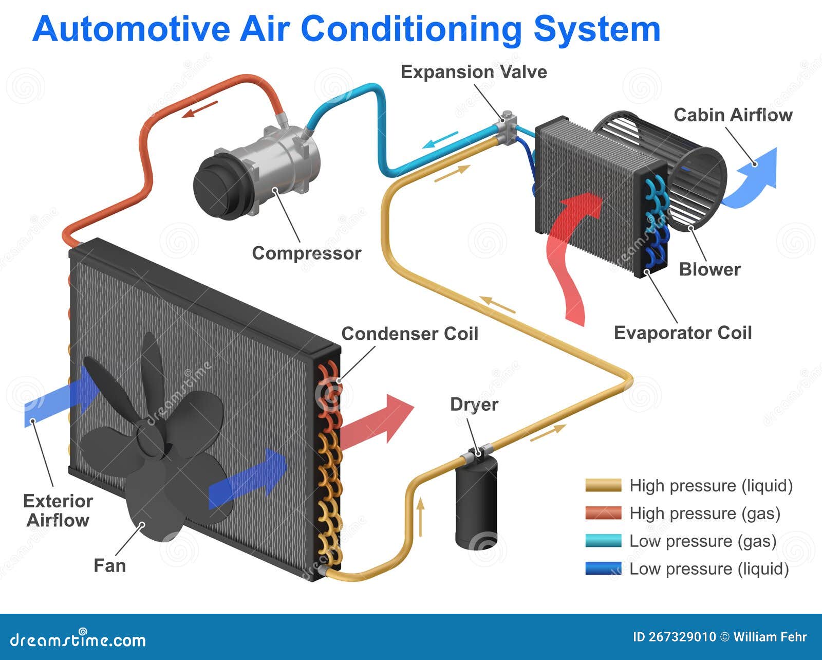
How It Works: The Refrigeration Cycle
The A/C system operates on a closed-loop refrigeration cycle. Here's a simplified explanation:
- Compression: The compressor takes low-pressure, low-temperature refrigerant gas and compresses it into high-pressure, high-temperature gas.
- Condensation: The high-pressure, high-temperature gas flows to the condenser, where it releases heat to the surrounding air and condenses into a high-pressure liquid.
- Metering: The high-pressure liquid refrigerant passes through the receiver-drier (or accumulator) for filtering and moisture removal, and then flows to the expansion valve (or orifice tube). The expansion valve regulates the flow of refrigerant into the evaporator and causes a pressure drop, lowering the refrigerant's temperature.
- Evaporation: The low-pressure, low-temperature liquid refrigerant enters the evaporator, where it absorbs heat from the cabin air and evaporates into a low-pressure, low-temperature gas.
- Return: The low-pressure, low-temperature gas returns to the compressor, completing the cycle.
Real-World Use: Basic Troubleshooting
Using the diagram, you can perform basic troubleshooting:
- No Cold Air: Check the compressor clutch engagement. If the clutch isn't engaging, investigate the pressure switches or electrical connections. The diagram helps you locate these components.
- Weak Airflow: Inspect the blower motor and its resistor. The diagram shows the location of the blower motor within the HVAC unit.
- Leaks: Look for signs of refrigerant leaks (oily residue) around fittings and connections. The diagram helps you identify all potential leak points. Use an electronic leak detector or UV dye (with appropriate safety precautions) to pinpoint the source.
- Strange Noises: Unusual noises from the compressor might indicate internal damage. The diagram confirms the compressor's location and allows you to visually inspect it.
Safety: A Word of Caution
Working with A/C systems can be dangerous. Refrigerant is a hazardous substance and can cause frostbite or asphyxiation. High pressures within the system can lead to component failure and potential injury.
- Never disconnect refrigerant lines without properly evacuating the system using a recovery machine.
- Wear appropriate personal protective equipment (PPE), including safety glasses and gloves.
- Be aware of the high-pressure components, especially the compressor and condenser.
- If you are not comfortable working with refrigerant, consult a qualified A/C technician.
By understanding the A/C system diagram, you can significantly enhance your ability to diagnose and maintain your car's air conditioning system. Remember to always prioritize safety and consult a professional when necessary.
For your convenience, we have a downloadable A/C system diagram file available. It includes detailed illustrations and component identification for common automotive A/C systems. This will be a valuable asset in your DIY projects and troubleshooting efforts.