
Diagram Chevy Rear Drum Brake Assembly
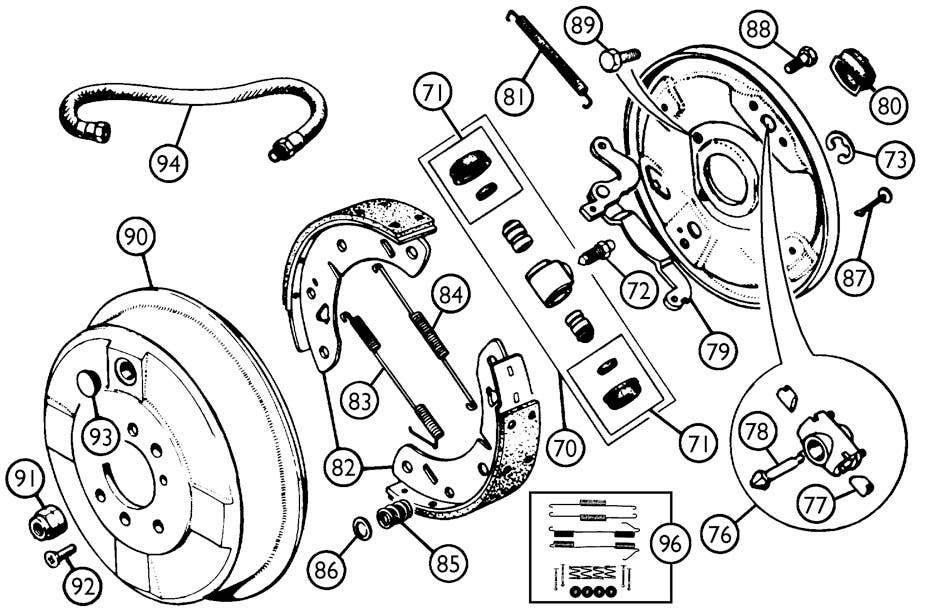
Rear drum brakes, while becoming less common on newer vehicles, remain a staple in many older cars and trucks, particularly Chevys. Understanding their assembly and operation is crucial for proper maintenance, repair, and even for those looking to upgrade or modify their braking system. This guide provides a detailed look at a typical Chevy rear drum brake assembly diagram, equipping you with the knowledge to confidently tackle related projects.
Purpose of Understanding the Diagram
A detailed diagram of the rear drum brake assembly isn't just a pretty picture; it's an essential tool for several reasons:
- Repairs and Maintenance: Accurately identifying components allows for precise ordering of replacement parts. Instead of guessing what "that little springy thing" is called, you can pinpoint it on the diagram and order with confidence.
- Troubleshooting: When diagnosing brake problems (like squealing, grabbing, or uneven braking), the diagram helps you isolate the potential source. For example, a broken return spring is easily identifiable.
- Assembly/Disassembly: If you're tackling a complete brake job or upgrading components, the diagram serves as a roadmap, ensuring you put everything back together correctly. This is especially critical for the complex spring arrangements.
- Learning and Understanding: Even if you're not planning immediate work, understanding the diagram deepens your knowledge of how your car's braking system functions.
Key Specs and Main Parts of a Chevy Rear Drum Brake Assembly
While specific dimensions will vary by Chevy model and year, the general components and their functions remain consistent. Let's break down the key parts:
Main Components:
- Brake Drum: The rotating cylindrical component that the brake shoes press against to create friction and slow the vehicle. It's typically made of cast iron.
- Brake Shoes: These are curved metal platforms with friction material (brake linings) bonded to their surfaces. They press outward against the inside of the drum.
- Wheel Cylinder: A hydraulic cylinder located at the top of the brake assembly. When you press the brake pedal, hydraulic pressure forces the pistons inside the wheel cylinder outward, pushing the brake shoes against the drum.
- Return Springs: These springs retract the brake shoes away from the drum when the brake pedal is released. There are typically two return springs, a primary and a secondary.
- Hold-Down Springs: Small springs and pins that hold the brake shoes against the backing plate, preventing them from rattling and ensuring proper alignment.
- Adjuster Assembly: A mechanism that automatically adjusts the clearance between the brake shoes and the drum as the brake linings wear down. This ensures consistent braking performance. Common types include star wheel adjusters.
- Parking Brake Lever and Strut: A lever connected to the parking brake cable. When engaged, it forces the brake shoes against the drum, holding the vehicle in place. The strut transmits the force from the lever to the secondary shoe.
- Backing Plate: A stationary metal plate that provides a mounting point for all the other components of the brake assembly.
Key Specs (General):
- Drum Diameter: Varies depending on the vehicle model. Important for selecting the correct replacement drums.
- Lining Thickness: The thickness of the friction material on the brake shoes. Should be within the manufacturer's specifications to ensure proper braking.
- Wheel Cylinder Bore Size: Affects the hydraulic pressure applied to the brake shoes.
- Spring Tension: Measured in pounds or Newtons. Important for ensuring proper shoe retraction and preventing brake drag.
Understanding Symbols in the Diagram
A good drum brake assembly diagram will use standardized symbols to represent different components and features. Here's a breakdown of some common ones:
- Solid Lines: Typically represent physical connections or boundaries of components.
- Dashed Lines: Often indicate hidden lines or components located behind other parts.
- Arrows: Indicate the direction of movement (e.g., the direction of the brake shoe when applied).
- Colors: While not always present, colors can be used to distinguish different systems or components. For example, hydraulic lines might be blue, while electrical wires are different colors based on function.
- Labels and Callouts: These are textual descriptions that identify specific components or provide additional information.
- Cutaway Views: A section of the diagram shows the internal workings of a component, such as the wheel cylinder.
How It Works: The Mechanics of Drum Brakes
The operation of a drum brake system is relatively simple, but understanding the sequence of events is key:
- Brake Pedal Activation: When you press the brake pedal, the master cylinder (located in the engine compartment) pressurizes the brake fluid.
- Hydraulic Pressure: This pressurized brake fluid travels through brake lines to the wheel cylinders at each wheel.
- Wheel Cylinder Activation: Inside the wheel cylinder, the hydraulic pressure pushes the pistons outward.
- Shoe Application: The pistons, in turn, push the brake shoes against the inside surface of the brake drum.
- Friction and Deceleration: The friction between the brake shoes and the drum slows the rotation of the drum, and consequently, the wheel.
- Release: When you release the brake pedal, the pressure in the hydraulic system drops. The return springs pull the brake shoes back away from the drum.
- Adjustment: As the brake linings wear, the adjuster assembly automatically extends to maintain the correct clearance between the shoes and the drum.
Many Chevy rear drum brake systems are of the "self-energizing" type. This means that the rotation of the drum helps to pull the primary shoe into the drum, increasing the braking force. This design can make these brakes very effective, but also sensitive to proper adjustment.
Real-World Use: Basic Troubleshooting Tips
Using the diagram, you can diagnose common drum brake problems:
- Squealing Brakes: Often caused by worn brake linings, glazed drums, or contaminated brake shoes. Inspect the linings and drums for wear and damage. Look for signs of brake fluid leaks.
- Grabbing Brakes: Can be caused by unevenly worn linings, a sticking wheel cylinder, or contaminated brake shoes. Check the wheel cylinder for leaks and ensure the shoes are moving freely.
- Uneven Braking: May indicate a problem with the wheel cylinder, brake lines, or adjuster assembly on one side of the vehicle. Bleeding the brakes may also be needed.
- Parking Brake Issues: If the parking brake doesn't hold, the cable may be stretched or broken, or the parking brake lever or strut may be damaged.
- Low Brake Pedal: Often indicates a leak in the hydraulic system or air in the brake lines. Check all brake lines, connections, and wheel cylinders for leaks.
If you're experiencing any of these issues, compare the parts against the brake diagram to identify broken parts or connections.
Safety Precautions
Working on brake systems requires caution. Here are some safety tips:
- Brake Fluid: Brake fluid is corrosive and can damage painted surfaces. Wear gloves and eye protection when handling it. Dispose of used brake fluid properly.
- Asbestos: Older brake linings may contain asbestos, a known carcinogen. If working on older brakes, take precautions to avoid inhaling dust. Wet the components down before disassembly to minimize dust.
- Springs: Brake springs are under tension and can be dangerous if not handled carefully. Use a brake spring tool to safely remove and install them.
- Wheel Cylinder: When disconnecting brake lines from the wheel cylinder, be prepared for brake fluid to leak out. Have a container ready to catch the fluid.
- Secure the Vehicle: Always use jack stands to support the vehicle when working underneath it. Never rely solely on a jack.
- Proper Reassembly: Ensure all components are properly installed and torqued to the manufacturer's specifications. Incorrect assembly can lead to brake failure.
Remember, when in doubt, consult a qualified mechanic.
We have a high-resolution, downloadable diagram of a typical Chevy rear drum brake assembly available. It provides a clearer visual representation of all the components discussed above. Access to this diagram is a great asset when working on your vehicle.