Diagram Coolant Temperature Sensor Location Manual
Understanding your vehicle's cooling system is crucial for maintaining optimal engine performance and preventing costly repairs. A vital component within this system is the Coolant Temperature Sensor (CTS). Having access to a reliable Coolant Temperature Sensor Location Diagram can be incredibly beneficial, whether you're performing routine maintenance, troubleshooting engine issues, or even embarking on performance modifications. This article will guide you through the anatomy of such a diagram, explaining its purpose, key components, symbols, and real-world applications, empowering you to diagnose and potentially resolve issues yourself.
Purpose of a Coolant Temperature Sensor Location Diagram
A Coolant Temperature Sensor Location Diagram serves several essential purposes:
- Repair and Maintenance: The primary reason to consult this diagram is to locate the CTS quickly and accurately for replacement or testing. Knowing its precise location saves time and prevents accidental damage to other components.
- Troubleshooting: When experiencing engine overheating, poor fuel economy, or difficulty starting, the CTS is often a suspect. The diagram helps you pinpoint the sensor for testing its functionality.
- Performance Modifications: Modders often use CTS data for engine management tuning. The diagram helps in understanding how the CTS integrates with the engine control unit (ECU) and other sensors.
- Learning and Understanding: Even if you're not currently facing any issues, studying the diagram can deepen your understanding of your vehicle's cooling system and sensor layout.
Key Specs and Main Parts Highlighted in the Diagram
A typical Coolant Temperature Sensor Location Diagram will showcase the following key specifications and parts:
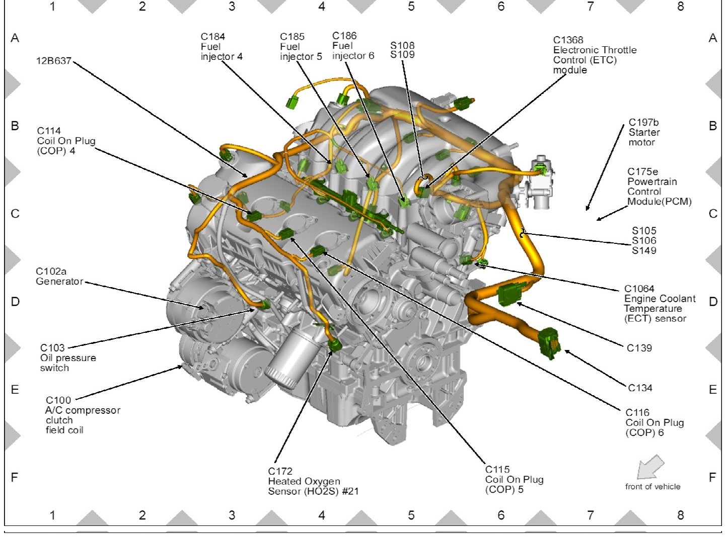
- Coolant Temperature Sensor (CTS): The sensor itself. Typically, the diagram will pinpoint its exact location on the engine block, cylinder head, or coolant passage. Often, different engine types will have different sensor locations, so it's critical that the diagram specifically matches your engine.
- Wiring Harness and Connector: The diagram will illustrate the wiring harness connected to the CTS, highlighting the connector type and wire colors. This is especially useful when diagnosing wiring issues or performing sensor replacements. The diagram might show the pinout diagram for the connector.
- Engine Block/Cylinder Head: The diagram will show the engine block or cylinder head to orient the CTS's location in relation to other engine components. This provides context and helps you physically locate the sensor.
- Coolant Passages: The diagram may show coolant passages and the flow of coolant to illustrate the sensor's placement within the cooling system.
- Grounding Points: The diagram might identify nearby grounding points, which are essential for the CTS to function correctly. Faulty grounds can cause inaccurate readings.
- Related Sensors: Some diagrams show the relative location of other sensors, such as the thermostat and temperature gauge sensor, to provide a more comprehensive view of the cooling system.
Key specifications often included are the thread size of the CTS, the recommended torque for tightening it, and the type of coolant compatible with the sensor.
Understanding the Symbols Used in the Diagram
Understanding the symbols used in the diagram is crucial for its interpretation. Here's a breakdown of common symbols:
- Lines:
- Solid Lines: Typically represent physical connections, such as coolant hoses or wiring harnesses.
- Dashed Lines: May represent hidden components or less critical connections.
- Colored Lines: Indicate specific wire colors in the wiring harness. A legend will usually explain the color codes (e.g., Red = 12V+, Black = Ground).
- Colors:
- Red: Often indicates a power source or positive voltage.
- Black: Commonly represents ground or negative voltage.
- Blue/Green/Yellow: Typically represent signal wires carrying data from the sensor to the ECU.
- Icons:
- Resistor Symbol (Zigzag Line): May indicate a built-in resistor within the sensor circuit.
- Ground Symbol (Stacked Horizontal Lines): Identifies grounding points.
- Connector Symbol (Rectangle with Pins): Represents the connector where the wiring harness plugs into the CTS.
Pay close attention to the diagram's legend or key, as it will provide specific explanations for the symbols used. A schematic diagram might be included to show the electrical relationship of the CTS in the overall engine control system.
How the Coolant Temperature Sensor Works
The Coolant Temperature Sensor is a thermistor, a type of resistor whose resistance changes significantly with temperature. Specifically, it's usually a Negative Temperature Coefficient (NTC) thermistor, meaning its resistance decreases as the coolant temperature increases. The CTS is immersed in the engine coolant. As the coolant temperature changes, the CTS's resistance changes. The Engine Control Unit (ECU) sends a small voltage to the CTS and measures the voltage drop across the sensor. Because the resistance of the sensor changes with temperature, the voltage returning to the ECU also changes. The ECU then uses this voltage reading to determine the coolant temperature. This information is crucial for:
- Fuel Injection: The ECU adjusts the air-fuel mixture based on coolant temperature. A cold engine requires a richer mixture.
- Ignition Timing: The ECU adjusts ignition timing for optimal performance.
- Idle Speed Control: The ECU controls idle speed based on engine temperature.
- Cooling Fan Activation: The ECU activates the cooling fan to prevent overheating.
- Temperature Gauge: The ECU sends a signal to the temperature gauge on the dashboard.
Real-World Use: Basic Troubleshooting Tips
Using the Coolant Temperature Sensor Location Diagram for troubleshooting:
- Locate the CTS: Use the diagram to pinpoint the exact location of the CTS on your engine.
- Inspect the Wiring: Visually inspect the wiring harness and connector for any signs of damage, corrosion, or loose connections. A multimeter can be used to check for continuity.
- Test the Sensor:
With the engine cold, disconnect the connector from the CTS. Use a multimeter set to measure resistance. Refer to your vehicle's service manual or online resources for the expected resistance values at specific temperatures. If the measured resistance is significantly different, the sensor may be faulty.
- Check for Voltage: With the ignition on (but engine off), use a multimeter to check for voltage at the CTS connector. There should be a small voltage (typically 5V) on one of the wires. If there's no voltage, there may be a wiring problem or an issue with the ECU.
- Scan for Codes: Use an OBD-II scanner to check for diagnostic trouble codes (DTCs) related to the CTS (e.g., P0115, P0116, P0117, P0118). These codes can provide valuable clues about the nature of the problem.
- Compare Readings: Some advanced scan tools allow you to monitor the CTS reading in real-time. Compare this reading to the actual engine temperature to see if there's a discrepancy.
Safety Precautions
Working with your vehicle's cooling system involves certain risks:
- Hot Coolant: Never work on the cooling system while the engine is hot. Coolant can be under pressure and can cause severe burns. Allow the engine to cool completely before attempting any repairs.
- Electrical Components: Disconnect the negative battery terminal before working on any electrical components, including the CTS.
- Sharp Objects: Be careful when working around engine components, as there may be sharp edges.
- Dispose of Coolant Properly: Coolant is toxic. Never pour it down the drain or onto the ground. Dispose of it properly at a recycling center or hazardous waste facility.
The CTS itself is not usually considered a high-risk component in terms of shock hazard (as it operates on low voltage), but the surrounding components, especially the engine and coolant, pose significant risks if not handled with care. Remember to always consult your vehicle's service manual for specific safety instructions and precautions.
With the knowledge gained from this article and the assistance of a detailed Coolant Temperature Sensor Location Diagram, you're well-equipped to diagnose and address potential issues with your vehicle's cooling system.
We have the file for a generic coolant temperature sensor location diagram that you can download. Please reach out to us for access to the file, and remember that while this is a general guide, always refer to your vehicle's specific service manual for accurate and safe repair procedures. Always double-check that the diagram accurately represents your specific vehicle's make, model, and year.