Diagram Detroit 60 Series Sensor Locations
For the seasoned DIY mechanic or aspiring diesel technician, understanding the sensor layout on a Detroit Diesel Series 60 engine is absolutely crucial. Whether you're diagnosing a pesky fault code, tackling a performance upgrade, or simply expanding your knowledge, knowing where each sensor is located and what it does can save you time, frustration, and money. This guide provides a detailed breakdown of the Series 60 sensor locations, their functions, and some basic troubleshooting tips.
Why This Diagram Matters
Think of a Detroit Diesel Series 60 sensor diagram as your engine's nervous system map. It allows you to:
- Diagnose Engine Issues: Quickly identify and locate the source of error codes. Knowing the sensor's location allows for focused testing and replacement.
- Perform Maintenance: Gain a better understanding of the engine's operating parameters, leading to more effective preventative maintenance.
- Execute Performance Upgrades: Modify sensor inputs or outputs for performance enhancements (with caution!). Understanding the sensor network is critical to avoid unintended consequences.
- Educational Purposes: Deepen your knowledge of diesel engine technology and control systems.
- Simplify Repairs: Accurately locate sensors needing replacement, avoiding unnecessary disassembly of other components.
Key Specs and Main Parts
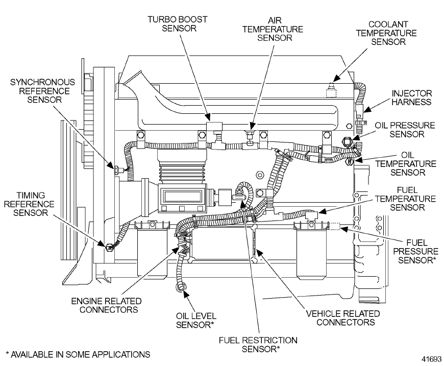
The Detroit Diesel Series 60 is a heavy-duty, in-line six-cylinder diesel engine used in a wide range of applications, including trucks, buses, and industrial equipment. While there might be some slight variations depending on the specific model year and configuration (e.g., EGR vs. non-EGR), the core sensor layout remains relatively consistent. Key sensors you'll typically find include:
- Engine Coolant Temperature (ECT) Sensor: Measures the temperature of the engine coolant.
- Oil Pressure Sensor: Monitors engine oil pressure.
- Intake Manifold Temperature (IMT) Sensor: Measures the temperature of the air entering the intake manifold.
- Intake Manifold Pressure (IMP) Sensor (also called Boost Pressure Sensor): Measures the pressure of the air in the intake manifold, indicating turbocharger boost.
- Crankshaft Position (CKP) Sensor: Provides the ECM with crankshaft position information for timing and RPM calculation.
- Camshaft Position (CMP) Sensor: Provides the ECM with camshaft position information, crucial for proper fuel injection timing.
- Fuel Temperature Sensor: Measures the temperature of the fuel.
- Exhaust Gas Recirculation (EGR) Valve Position Sensor (on EGR-equipped models): Monitors the position of the EGR valve.
- Turbocharger Speed Sensor: Monitors the rotational speed of the turbocharger.
- Ambient Air Temperature Sensor: Measures the temperature of the outside air.
The Electronic Control Module (ECM) is the brains of the operation. It receives signals from all these sensors, processes the information, and controls various engine actuators, such as fuel injectors and the EGR valve. Understanding the communication between sensors and the ECM is fundamental to diagnosing complex engine problems.
Symbols and Conventions in Sensor Diagrams
A good Series 60 sensor diagram will utilize standard symbols to represent different components and connections. Here's a breakdown of common symbols:
- Solid Lines: Typically represent wiring harnesses or electrical connections.
- Dashed Lines: May indicate vacuum lines or other types of fluid lines.
- Sensor Icons: Standardized icons represent each type of sensor (ECT, oil pressure, etc.). These icons are usually labelled with abbreviations.
- Connector Symbols: Represent electrical connectors. These are vital for identifying connection points when tracing wiring issues.
- Ground Symbols: Indicate grounding points for sensors and other electrical components. A clean, solid ground is crucial for accurate sensor readings.
- Colors: Wire colors are often included on wiring diagrams, aiding in identifying specific wires within a harness.
Pay close attention to the legend or key provided with the diagram, as specific symbols and color codes may vary slightly depending on the source of the diagram.
How It Works: The Sensor Network
Each sensor plays a specific role in monitoring engine parameters and providing feedback to the ECM. Here's a simplified overview of how it works:
- Sensing: The sensor detects a specific physical quantity (temperature, pressure, position, etc.).
- Signal Conversion: The sensor converts the physical quantity into an electrical signal (voltage or resistance).
- Signal Transmission: The electrical signal is transmitted to the ECM via wiring.
- Data Processing: The ECM interprets the signal and uses it to make decisions about engine control.
- Actuation: The ECM sends signals to actuators (fuel injectors, EGR valve, etc.) to adjust engine parameters based on sensor data.
For instance, the ECT sensor monitors engine coolant temperature. If the coolant temperature gets too high, the ECM might reduce fuel delivery or activate the cooling fan to prevent overheating. Similarly, the IMP sensor monitors turbocharger boost pressure. If the boost pressure is too high, the ECM might adjust fuel delivery to prevent engine damage.
Real-World Use: Basic Troubleshooting Tips
Here are some basic troubleshooting tips using the sensor diagram:
- Check Engine Light (CEL): If the CEL is illuminated, use a diagnostic scan tool to retrieve the Diagnostic Trouble Code (DTC). Consult the sensor diagram to locate the sensor associated with the DTC.
- Wiring Inspection: Visually inspect the wiring harness and connectors for the sensor for any signs of damage, corrosion, or loose connections.
- Sensor Testing: Use a multimeter to check the sensor's resistance or voltage output. Compare the readings to the manufacturer's specifications.
- Signal Tracing: Use the wiring diagram to trace the signal from the sensor to the ECM. This can help identify breaks or shorts in the wiring.
- Sensor Replacement: If the sensor is faulty, replace it with a new one. Ensure the replacement sensor is compatible with your engine model.
Example: Let's say you get a DTC indicating a problem with the Intake Manifold Temperature (IMT) sensor. Using the diagram, you locate the IMT sensor on the intake manifold. You then inspect the wiring and connector for any damage. If the wiring appears to be okay, you can use a multimeter to check the sensor's resistance. If the resistance is outside the specified range, you likely need to replace the sensor.
Safety Considerations
Working on a diesel engine involves inherent risks. Here are some safety precautions to keep in mind:
- Disconnect the Battery: Before working on any electrical components, disconnect the battery to prevent electrical shock.
- High-Pressure Fuel System: The fuel system operates at very high pressures. Never disconnect fuel lines without properly relieving the pressure first.
- Hot Surfaces: Be careful of hot engine components, especially the exhaust manifold and turbocharger.
- Proper Tools: Use the correct tools for the job to avoid damaging components or injuring yourself.
- Diesel Fuel Handling: Diesel fuel is flammable and can be harmful if ingested or inhaled. Wear gloves and eye protection when handling fuel.
Always consult the manufacturer's service manual for specific safety instructions and procedures.
We have a comprehensive Detroit Diesel Series 60 sensor diagram available for download. With this diagram, you'll have the necessary tool to navigate your Series 60's sensor network with confidence.