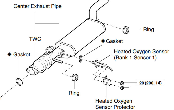
Diagram Downstream O2 Sensor Location
Understanding the location and function of your downstream oxygen (O2) sensor is crucial for maintaining your vehicle's performance, fuel efficiency, and emissions compliance. This article provides a detailed guide to interpreting diagrams related to downstream O2 sensor placement, function, and common issues. Whether you're tackling a repair, modifying your exhaust system, or simply expanding your automotive knowledge, this information will prove invaluable. We also have a detailed diagram file ready for you to download, offering a visual aid to complement this guide.
Purpose of Understanding Downstream O2 Sensor Diagrams
Downstream O2 sensor diagrams are essential for several reasons:
- Diagnostics: Accurately identifying the sensor's location is the first step in diagnosing related error codes (e.g., P0137, P0138, P0140, P0141).
- Repairs: Knowing the precise location and connections allows for efficient sensor replacement or wiring repairs.
- Modifications: When modifying exhaust systems (e.g., installing aftermarket catalytic converters or headers), you need to understand the downstream sensor's placement to ensure proper functionality and avoid triggering check engine lights.
- Learning: Studying these diagrams deepens your understanding of the entire exhaust and emissions control system.
Key Specs and Main Parts of a Downstream O2 Sensor System
Before diving into diagrams, let's define the key components and specifications:
Main Parts:
- Downstream O2 Sensor (also called Post-Cat O2 Sensor): The sensor located *after* the catalytic converter. It primarily monitors the converter's efficiency.
- Wiring Harness: Connects the sensor to the Engine Control Unit (ECU). Typically consists of multiple wires (usually 4) providing power, ground, sensor signal, and sensor heater control.
- Connector: The electrical connector that links the sensor to the wiring harness.
- Catalytic Converter: The device that reduces harmful emissions from the exhaust gases. The downstream O2 sensor monitors its functionality.
- Exhaust Pipe: The piping where the downstream sensor is mounted.
- ECU (Engine Control Unit): The car's computer that interprets the signals from the O2 sensors and adjusts engine parameters.
Key Specifications:
- Voltage Range: Typically 0-1 Volt. A healthy downstream sensor should show a relatively stable voltage, indicating a consistent oxygen level after the catalytic converter.
- Resistance (Heater Circuit): The heater circuit within the sensor has a specific resistance value. An open or shorted heater circuit will trigger a DTC (Diagnostic Trouble Code).
- Sensor Type: Most modern vehicles use zirconia or titania O2 sensors. Diagrams usually don't specify the type directly but the context indicates which kind is used.
- Thread Size: The size of the threads used to screw the sensor into the exhaust pipe (typically 18mm).
- Torque Specification: The recommended torque for tightening the sensor (important to avoid damage).
Interpreting Symbols in Downstream O2 Sensor Diagrams
Understanding the symbols used in these diagrams is crucial for accurate interpretation. Here are some common symbols and their meanings:
- Solid Lines: Represent physical connections, such as wiring. Thicker lines might denote power or ground wires.
- Dashed Lines: Often represent communication pathways or signal lines between the sensor and the ECU.
- Color Coding: Wiring diagrams use color codes to identify individual wires. Common colors include black (ground), red (power), white (sensor signal), and blue/green (heater circuit). Refer to the specific vehicle's wiring diagram for the correct color assignments.
- Sensor Symbol: Typically a circle with an embedded resistive element symbol. The sensor is typically labeled as "HO2S" (Heated Oxygen Sensor) or "O2 Sensor." The diagram also indicates whether it is upstream (before catalytic converter) or downstream (after catalytic converter).
- Connector Symbol: A rectangular box or a series of interlocking shapes representing the electrical connector. It often includes pin numbers to identify individual wire connections.
- ECU Symbol: Usually a rectangular box labeled "ECU" or "PCM" (Powertrain Control Module).
- Ground Symbol: Represents the grounding point for the sensor and other components.
Important: Always refer to the specific vehicle's service manual or wiring diagram for the most accurate and detailed information on symbols and color coding. Generic diagrams may not perfectly match your vehicle's configuration.
How the Downstream O2 Sensor Works
The downstream O2 sensor plays a crucial role in monitoring the performance of the catalytic converter. It measures the amount of oxygen present in the exhaust gases *after* they have passed through the converter. Here's a breakdown:
- Oxygen Measurement: The sensor contains a ceramic element that generates a voltage based on the difference in oxygen concentration between the exhaust gases and the surrounding air.
- Signal Transmission: This voltage signal is sent to the ECU.
- Catalytic Converter Efficiency Assessment: The ECU compares the signal from the downstream sensor to the signal from the upstream sensor (located before the catalytic converter). A properly functioning catalytic converter will significantly reduce the oxygen content in the exhaust. Therefore, the downstream sensor should show a relatively stable voltage (close to 0.7-0.9V), indicating a lean mixture (low oxygen content).
- Fault Detection: If the downstream sensor's voltage fluctuates similarly to the upstream sensor, it indicates that the catalytic converter is not functioning efficiently. This will trigger a check engine light and a corresponding DTC.
- Heater Circuit: The O2 sensor requires a certain operating temperature to function accurately. A heater circuit within the sensor quickly brings it up to temperature, allowing for accurate readings even during cold starts.
Real-World Use: Basic Troubleshooting Tips
Here are some common issues and troubleshooting tips related to the downstream O2 sensor:
- Check Engine Light (CEL) with O2 Sensor Codes: Use an OBD-II scanner to retrieve the specific code. Common codes include P0137, P0138, P0140, P0141, and codes indicating catalytic converter inefficiency (e.g., P0420).
- Sensor Replacement: If the sensor is faulty, replace it with a new one that is compatible with your vehicle. Ensure the new sensor is properly tightened to the correct torque specification.
- Wiring Issues: Inspect the wiring harness and connector for damage, corrosion, or loose connections. Use a multimeter to check for continuity and voltage at the connector.
- Exhaust Leaks: Exhaust leaks near the sensor can affect its readings. Inspect the exhaust system for leaks and repair them as needed.
- Catalytic Converter Failure: A failing catalytic converter will often trigger downstream O2 sensor codes. Consider replacing the catalytic converter if it is determined to be the root cause of the problem.
- Sensor Contamination: Oil, coolant, or fuel contamination can damage the sensor. Identify and address the source of the contamination.
Safety Considerations
Working with automotive electrical systems and exhaust components involves inherent risks. Always prioritize safety:
- Disconnect the Battery: Before working on any electrical components, disconnect the negative battery cable to prevent accidental short circuits.
- Hot Exhaust: Exhaust pipes can get extremely hot. Allow the exhaust system to cool down completely before working on it.
- Electrical Shock: Exercise caution when working with electrical wiring. Avoid touching exposed wires.
- Protective Gear: Wear safety glasses, gloves, and appropriate clothing to protect yourself from burns, cuts, and chemical exposure.
- Proper Tools: Use the correct tools for the job. Improper tools can damage components or cause injury. An O2 sensor socket is highly recommended.
We hope this guide provided a solid understanding of downstream O2 sensor diagrams and their practical application. Remember, diagnosing and repairing emissions-related issues can be complex. If you're not comfortable performing the work yourself, consult a qualified mechanic. For a detailed visual representation, we have the downstream O2 sensor diagram file ready for you to download. It's a valuable resource to further enhance your understanding!