Diagram Ford F150 Ground Wire Location Pdf
For the seasoned DIY mechanic tackling electrical work on a Ford F-150, a reliable ground wire location diagram is absolutely invaluable. Whether you're diagnosing a parasitic drain, installing aftermarket accessories, or simply performing routine maintenance, understanding the grounding system is critical for success and safety. We have the Ford F-150 ground wire location diagram available for download, allowing you to get hands-on with your vehicle. Before diving in, let's explore what this diagram offers and how to use it effectively.
Purpose and Importance of Ground Wire Diagrams
A ground wire location diagram serves several crucial purposes:
- Diagnosis and Repair: It allows you to quickly locate ground points suspected of corrosion or damage, which can cause a wide range of electrical problems.
- Component Identification: It helps you identify which components share a common ground, aiding in the diagnosis of issues affecting multiple systems.
- Aftermarket Installation: When adding accessories like lights, stereos, or alarms, the diagram helps you find suitable grounding points to ensure proper operation and prevent ground loops.
- Learning and Understanding: Studying the diagram allows you to better understand the electrical system architecture of your F-150.
Without it, you're essentially troubleshooting blind, wasting time and potentially causing further damage. Think of it as the roadmap to the electrical nervous system of your truck.
Key Specs and Main Parts Depicted
A typical F-150 ground wire location diagram will show the following key elements:
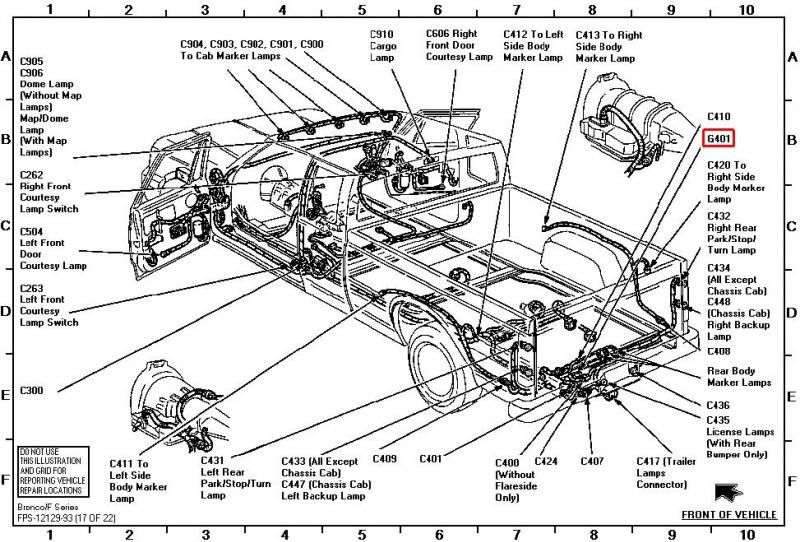
- Ground Points: Represented by symbols (typically a triangle pointing downwards connected to horizontal lines), these indicate the physical locations where ground wires are attached to the chassis or body of the vehicle. Each ground point usually has a unique identifier (e.g., G101, G205).
- Ground Wires: Lines connecting the ground points to the various electrical components and modules. The thickness and color of these lines may indicate wire gauge and function.
- Components: A simplified representation of electrical components like the PCM (Powertrain Control Module), BCM (Body Control Module), lamps, sensors, and actuators.
- Wiring Harnesses: Groups of wires bundled together, often indicated by a thicker line or a shaded area. Understanding the harness layout is crucial for tracing wires.
- Connectors: Where wires are joined together, represented by symbols (often a circle or a square with lines connecting to it). Connector locations are also typically labeled.
The diagram will also likely include specifications such as the wire gauge (AWG - American Wire Gauge) used for different circuits and the torque specifications for ground bolts. Always refer to the specific diagram for your F-150's model year as there can be significant variations.
Decoding the Symbols and Color Codes
Understanding the symbols and color codes used in the diagram is paramount. Here's a breakdown:
- Ground Symbols: As mentioned, the downward-pointing triangle is the standard ground symbol. Multiple horizontal lines below it might indicate the quality or robustness of the ground connection.
- Lines: Solid lines represent wires. Dashed lines often indicate shielded wires or wires that are part of a network (like CAN - Controller Area Network).
- Colors: Wire colors are typically indicated by abbreviations (e.g., BK for Black, WH for White, GN for Green, BU for Blue, RD for Red, YE for Yellow). Combinations indicate a wire with a stripe of another color (e.g., BK/WH for Black with White stripe).
- Component Symbols: These are often simplified representations of the actual components. A rectangle might represent a relay, a circle with a line through it might represent a lamp, and so on. Consult the legend on the diagram for clarification.
- Connectors: Typically, a small circle or square with lines emanating from it. The number of lines indicates the number of wires connected to it. Connector numbers are vitally important for locating the physical connector.
Pay close attention to the legend provided with the diagram. This will explain any non-standard symbols or abbreviations used.
How the Grounding System Works
The grounding system in your F-150 is designed to provide a low-resistance path for electrical current to return to the battery's negative terminal. This is essential for the proper operation of all electrical components. Without a solid ground, circuits become incomplete, leading to malfunction or failure.
The negative battery terminal is connected to the chassis of the truck, usually via a heavy-gauge cable. From the chassis, a network of ground wires extends to various components and modules. These ground wires provide a return path for the current that flows through those components.
Why is a good ground so important? Electricity always seeks the path of least resistance. A corroded or loose ground connection will increase resistance, forcing current to find an alternate path, potentially through sensitive electronic components, causing damage. This can also result in voltage drops, leading to dim lights, weak signals, and erratic behavior of electrical systems.
Ford often uses a "star grounding" system, where multiple components share a common ground point. This reduces the likelihood of ground loops, which can introduce noise into the electrical system.
Real-World Use: Basic Troubleshooting
Here's how you can use the ground wire diagram for troubleshooting:
- Identify the Symptom: Determine the specific electrical problem you're experiencing (e.g., a malfunctioning sensor, dim headlights, a parasitic battery drain).
- Consult the Diagram: Locate the components involved in the affected circuit on the ground wire diagram.
- Identify Shared Grounds: Check if those components share a common ground point. If they do, that ground point is a prime suspect.
- Inspect the Ground Point: Physically locate the ground point on the truck (using the diagram as your guide). Visually inspect it for corrosion, looseness, or damage.
- Test Continuity: Use a multimeter to test the continuity between the ground point and the chassis. You should have very low resistance (close to 0 ohms). High resistance indicates a bad ground.
- Clean and Tighten: If the ground point is corroded, clean it with a wire brush and electrical contact cleaner. Tighten the ground bolt to the specified torque.
For example, if you're experiencing issues with multiple lights on the rear of the truck, consult the diagram to see if they share a common ground. If they do, focus your troubleshooting efforts on that ground point.
A common issue on older F-150s is corroded ground points under the hood and along the frame rails. These areas are exposed to moisture and road salt, which can accelerate corrosion.
Sometimes, a parasitic drain on the battery can be traced to a faulty component improperly grounding through the chassis rather than designated ground point. Use the diagram to trace suspect components, disconnect them, and measure amperage draw again to identify the culprit.
Safety Precautions
Working with automotive electrical systems can be dangerous. Here are some essential safety precautions:
- Disconnect the Battery: Always disconnect the negative battery terminal before working on any electrical components. This prevents accidental shorts and potential electrical shock.
- Use Proper Tools: Use insulated tools to avoid short circuits.
- Avoid Water: Never work on electrical systems in wet conditions.
- Be Aware of Airbags: Exercise extreme caution when working near airbag components. Disconnect the battery and wait at least 30 minutes before working on or near them. Accidental deployment can cause serious injury.
- High-Current Circuits: Be particularly careful when working with high-current circuits, such as those for the starter motor or alternator. These circuits can deliver a significant electrical shock.
Remember, if you're not comfortable working on electrical systems, it's best to consult a qualified mechanic.
Download Your F-150 Ground Wire Diagram
Now that you understand the importance of a ground wire location diagram and how to use it effectively, you're ready to get your hands dirty! We have the Ford F-150 ground wire location diagram ready for you to download and begin diagnosing and repairing your electrical system.