
Diagram Ford Fuel Pump Wires Color Codes
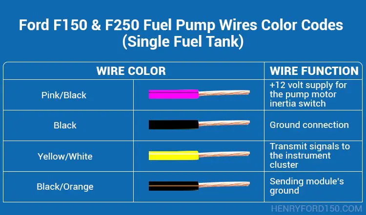
Understanding the wiring of your Ford fuel pump is crucial for various tasks, from diagnosing fuel delivery problems to performing fuel system upgrades. This guide will delve into the intricacies of Ford fuel pump wiring diagrams, focusing on color codes, common configurations, and troubleshooting techniques. Consider this your go-to resource for decoding the electrical language of your Ford's fuel pump.
Purpose of Understanding Ford Fuel Pump Wiring Diagrams
Why bother learning about fuel pump wiring? The answer is multifaceted. A clear understanding empowers you to:
- Diagnose Fuel Delivery Issues: Pinpoint electrical faults that prevent the pump from operating correctly.
- Perform Repairs: Accurately replace damaged wiring, connectors, or even the fuel pump itself.
- Undertake Modifications: Install aftermarket fuel pumps, fuel pressure regulators, or other fuel system components. This includes understanding relay logic for higher-capacity pumps.
- Prevent Catastrophic Failures: Identify potential short circuits or open circuits that could damage the fuel pump, fuel injection system, or even the vehicle's ECU (Engine Control Unit).
Key Specifications and Main Parts in a Ford Fuel Pump System
Before diving into the wiring diagram, let's review the key components of a typical Ford fuel pump system. These typically include:
- Fuel Pump: The heart of the system, responsible for drawing fuel from the tank and delivering it to the engine. Ford fuel pumps are typically electric and located inside the fuel tank (submersible) for cooling and noise reduction.
- Fuel Pump Relay: An electrically operated switch that controls power to the fuel pump. This allows the ECU to start/stop the pump.
- Inertia Switch (Fuel Shutoff Switch): A safety device designed to cut power to the fuel pump in the event of a collision. Also known as a fuel cutoff switch, this prevents fuel from being pumped if the car is in an accident.
- Fuel Pump Resistor (if equipped): Some older Ford models use a resistor to reduce voltage to the fuel pump at lower engine speeds. This is typically bypassed during engine starting and at higher RPMs to ensure sufficient fuel delivery.
- Fuel Filter: Cleans fuel before it enters the engine.
- Fuel Pressure Regulator: Maintains a consistent fuel pressure in the fuel rail.
- Wiring Harness: Connects all the components, including power and ground connections.
- ECU (Engine Control Unit): The "brain" of the system. The ECU commands the fuel pump relay based on engine speed, load, and other sensor inputs.
Understanding Fuel Pump Wiring Diagram Symbols and Color Codes
A wiring diagram is a symbolic representation of the electrical circuit. Here's how to interpret the key elements:
Lines:
- Solid Lines: Indicate a wire. The thickness of the line doesn't necessarily indicate wire gauge.
- Dashed Lines: May represent shielding or a ground connection.
- Lines Crossing: A simple intersection of two wires. There is no electrical connection between them unless a dot (node) is present.
- Lines Joining with a Dot: An electrical connection (splice) between two or more wires.
Color Codes:
Ford uses standardized color codes to identify wires. Here are some common ones, but always consult the specific wiring diagram for your vehicle:
- RD (Red): Typically a power wire.
- BK (Black): Typically a ground wire.
- TN (Tan): Often used for the fuel pump relay control signal from the ECU.
- PK (Pink): Sometimes used for fuel pump power.
- DB (Dark Blue): Can be used for various sensors or control signals.
- LG (Light Green): Commonly used for signals from sensors, or indicator lights.
- WH (White): Can be used for various sensor signals.
- YL (Yellow): Can be used for various power or signal wires.
It's also common to see two-color codes, such as RD/BK (Red with a Black stripe). The first color is the base color, and the second is the stripe color.
Icons:
- Rectangles: Represent components like relays, resistors, and the fuel pump itself.
- Circles: Can represent connectors or test points.
- Ground Symbol (usually three lines decreasing in length): Indicates a connection to the vehicle's chassis ground.
How the Ford Fuel Pump System Works
The basic operation is as follows:
- When the ignition key is turned to the "ON" position, the ECU briefly activates the fuel pump relay. This is a priming pulse to build fuel pressure before the engine starts.
- Once the engine starts, the ECU continuously monitors engine speed and load.
- Based on these inputs, the ECU signals the fuel pump relay to provide power to the fuel pump.
- The fuel pump draws fuel from the tank and delivers it to the fuel rail.
- The fuel pressure regulator maintains the correct fuel pressure in the rail.
- Excess fuel is returned to the fuel tank through a return line (in return-style fuel systems). Returnless systems regulate fuel pressure at the pump module within the fuel tank.
- The inertia switch acts as a safety backup, cutting power to the pump in the event of a collision.
Real-World Use: Basic Fuel Pump Troubleshooting
Here's how to use your knowledge of wiring diagrams to troubleshoot fuel pump problems:
- No Fuel Pump Operation:
- Check the fuel pump fuse. If it's blown, replace it and see if it blows again (indicating a short circuit).
- Locate the fuel pump relay. Test the relay by applying voltage to the coil terminals (refer to the wiring diagram for the correct terminals). You should hear a click, and you can test for continuity across the switched terminals.
- Check for voltage at the fuel pump connector when the ignition is turned on (or during the priming pulse). Use a multimeter to measure voltage between the power wire (typically RD or PK) and ground (BK).
- If there's no voltage, trace the wiring back to the fuel pump relay and the inertia switch, checking for broken or corroded wires and connectors.
- If there is voltage, but the pump still doesn't run, the fuel pump itself may be faulty.
- Low Fuel Pressure:
- Check the fuel filter for clogs.
- Check the fuel pressure regulator for proper operation.
- Inspect the fuel pump wiring and connectors for corrosion or damage. A corroded connection can reduce voltage to the pump, resulting in lower fuel pressure.
- If voltage and wiring is good, the fuel pump may be failing.
Safety Precautions
Working with fuel systems requires caution. Always remember:
- Fuel is Flammable: Disconnect the negative battery cable before working on the fuel system to prevent sparks.
- Fuel Pressure: Relieve fuel pressure before disconnecting any fuel lines. There is typically a Schrader valve on the fuel rail for releasing fuel pressure.
- Electrical Components: Be extremely careful when working with electrical components. Avoid short circuits.
- Inertia Switch: Some inertia switches are sensitive. Be careful not to accidentally trip the switch while working in the area.
Important Note on Electrical System Damage
Always consult the specific wiring diagram for your vehicle's year, make, and model. Wiring configurations can vary significantly. Incorrectly wiring a fuel pump can damage the fuel pump, the ECU, and other electrical components. Verify wire functions before modifying any wiring!
We have access to a library of Ford fuel pump wiring diagrams. Contact us to request the specific diagram for your Ford model.