Diagram Fuel Tank Pressure Sensor Location
Okay, so you're diving into the fuel system and need to pinpoint that fuel tank pressure (FTP) sensor. That's smart. Knowing its location, understanding how it works, and having a good diagram at your fingertips can save you a lot of headaches during repairs, modifications, or even just understanding your vehicle's emissions control system. This article will walk you through interpreting a typical FTP sensor location diagram, helping you troubleshoot potential issues. And yes, we have a downloadable diagram file ready for you at the end!
Purpose of Understanding the Fuel Tank Pressure Sensor Location
Why bother with this? Well, there are several reasons. Firstly, if you're getting a "Check Engine" light related to EVAP (Evaporative Emission Control) system errors – codes like P0440, P0451, P0452, P0453, P0455, etc. – the FTP sensor is often a prime suspect. Knowing its location allows you to:
Diagnose problems: Is it disconnected? Damaged? Is the wiring faulty?
Perform testing: Check the sensor's output voltage or resistance to see if it's within spec.
Replace the sensor: A relatively inexpensive fix that can resolve common EVAP issues.
Understand Modifications: When upgrading fuel pumps or making changes to the fuel system, the FTP sensor functionality must be maintained for proper engine operation and emissions compliance.
Furthermore, understanding the entire EVAP system, starting with the FTP sensor, gives you a much better understanding of how your car manages fuel vapor and prevents it from escaping into the atmosphere. This is crucial for meeting emissions standards and maintaining optimal fuel efficiency.
Key Specs and Main Parts of the Fuel Tank Pressure Sensor
Let's get down to the specifics. The FTP sensor, at its core, is a type of pressure transducer. It converts pressure readings into an electrical signal that the vehicle's Powertrain Control Module (PCM) can interpret. Here’s a breakdown of key aspects:
- Sensor Type: Typically a piezoresistive pressure sensor. This means it uses a material whose resistance changes when pressure is applied.
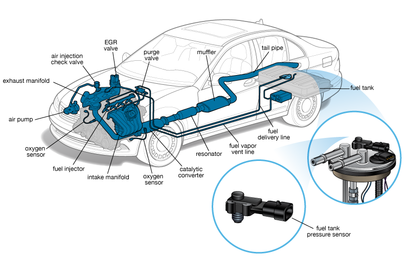
- Location: Usually mounted directly on the fuel tank, on the fuel pump module assembly, or inline in a vapor line connected to the fuel tank. The diagram will pinpoint the exact location for your vehicle.
- Output Signal: Usually a 0-5V DC signal. The voltage corresponds to the pressure inside the fuel tank. For example, 0V might represent vacuum, and 5V might represent high pressure.
- Operating Range: Varies by vehicle, but generally ranges from a vacuum of -0.5 psi to a positive pressure of +2.5 psi.
- Connector: A multi-pin connector (usually 3 or 4 pins) providing power, ground, and the signal output.
Main Parts of the System:
- Fuel Tank Pressure Sensor: The device itself.
- Wiring Harness: Connects the sensor to the PCM. Look for potential breaks, corrosion, or shorts.
- Fuel Tank: The container for the fuel.
- Fuel Pump Module: Often integrated with the fuel level sensor and sometimes the FTP sensor.
- EVAP Canister: Stores fuel vapors until they can be purged into the engine.
- Purge Valve: Controls the flow of fuel vapors from the canister to the engine.
- Vent Valve: Allows fresh air to enter the fuel tank, often located near the EVAP canister.
- PCM (Powertrain Control Module): The car's computer, which receives the signal from the FTP sensor and controls the EVAP system.
Understanding Symbols in the Diagram
A good FTP sensor location diagram will use standardized symbols. Here's how to interpret them:
- Solid Lines: Typically represent hard fuel lines or vapor lines.
- Dashed Lines: Often indicate vacuum lines or electrical wiring.
- Color Coding: May vary by manufacturer, but commonly, red wires are power, black are ground, and other colors are signal wires. Check the legend of the diagram for clarification.
- Component Symbols: The FTP sensor will usually be depicted as a small box or cylinder with lines indicating its electrical connection. Other components like the fuel tank, canister, and valves will have their own distinct symbols.
- Connectors: Illustrated as small circles or squares where wires or lines connect. These are important points to check for corrosion or loose connections.
- Arrows: Show the direction of flow for fuel or vapors.
Pay close attention to the legend accompanying the diagram. It's the key to accurately interpreting the symbols used in *that specific diagram*. Don't assume all diagrams use the exact same conventions.
How the Fuel Tank Pressure Sensor Works
The FTP sensor's job is to monitor the pressure (or vacuum) inside the fuel tank. As the fuel level changes, the temperature fluctuates, or the EVAP system performs its self-checks, the pressure inside the tank will vary. Here’s a simplified explanation:
- The FTP sensor is exposed to the pressure inside the fuel tank.
- The sensor's internal element, usually a piezoresistive material, deforms slightly in response to the pressure.
- This deformation causes a change in the electrical resistance of the element.
- The sensor converts this change in resistance into a voltage signal.
- The PCM reads this voltage signal and interprets it as a specific pressure reading.
- Based on this pressure reading, along with other inputs from sensors like the engine coolant temperature sensor and throttle position sensor, the PCM controls the EVAP system – opening and closing the purge and vent valves to maintain proper fuel vapor management.
The PCM uses this information to detect leaks in the EVAP system. For example, if the PCM commands the vent valve closed and the purge valve open to create a vacuum in the fuel tank, but the FTP sensor doesn't report a drop in pressure, it indicates a potential leak.
Real-World Use: Basic Troubleshooting Tips
Okay, let's say your "Check Engine" light is on, and you suspect the FTP sensor. Here's what you can do:
- Scan for Codes: Use an OBD-II scanner to read the diagnostic trouble codes (DTCs). Codes related to the EVAP system or FTP sensor (e.g., P0451, P0452, P0453) will point you in the right direction.
- Visual Inspection: Locate the FTP sensor using the diagram (the one we'll provide!). Check for any obvious damage, disconnected wires, or corroded terminals.
- Wiring Check: Use a multimeter to check the wiring harness for continuity (no breaks) and shorts to ground or power.
- Sensor Testing: With the key on, use a multimeter to measure the voltage at the signal wire. The voltage should change as you introduce a slight vacuum or pressure to the fuel tank (use a hand vacuum pump). Refer to your vehicle's service manual for the correct voltage range.
- Replacement: If the sensor is faulty, replace it. Follow the diagram and instructions carefully. Remember to disconnect the battery before working on any electrical components.
Common Issues:
Cracked or Damaged Sensor: Physical damage can render the sensor useless.
Corroded Connectors: Corrosion can impede the electrical signal.
Vacuum Leaks: Leaks in the EVAP lines can throw off the pressure readings.
Faulty Wiring: Broken or shorted wires can disrupt the signal.
Safety Considerations
Working with the fuel system always involves risks. Fuel is highly flammable, and fuel vapors are explosive. Here are some crucial safety precautions:
- Disconnect the Battery: This is paramount to prevent sparks and accidental electrical shorts.
- Work in a Well-Ventilated Area: Allow fuel vapors to dissipate.
- No Smoking or Open Flames: Absolutely no smoking or open flames near the fuel system.
- Use Proper Tools: Use fuel line disconnect tools to avoid damaging the fuel lines.
- Wear Safety Glasses: Protect your eyes from fuel splashes.
- Have a Fire Extinguisher Nearby: Just in case.
- Depressurize the Fuel System: Consult your vehicle's service manual for the proper procedure to relieve fuel pressure before disconnecting any fuel lines.
Remember, if you're not comfortable working on the fuel system, it's best to leave it to a qualified mechanic. Your safety is the top priority.
Now that you're armed with this information, you're well-equipped to understand and troubleshoot FTP sensor-related issues. Good luck with your repair!
We have that FTP sensor location diagram file we promised ready for download. Click here to download. Please note: this is a general diagram and might not perfectly represent *your* specific vehicle. Always consult your vehicle's service manual for the most accurate information.