Diagram Fusible Link Between Alternator And Battery
Understanding the fusible link between your alternator and battery is crucial for diagnosing electrical issues, performing safe repairs, and even planning modifications. This guide provides a detailed explanation of the circuit, covering its purpose, components, operation, troubleshooting, and most importantly, safety. Whether you're facing a dead battery, suspect an alternator problem, or simply want to deepen your automotive knowledge, this information will prove invaluable.
Purpose and Importance
The fusible link in the alternator-to-battery circuit serves as a vital safety device, protecting the electrical system from overcurrent conditions. These conditions can arise from various sources, including:
- Alternator Failure: A malfunctioning alternator can produce excessive voltage and current, potentially damaging other components.
- Short Circuits: A short circuit, where a live wire directly contacts the vehicle's chassis or ground, can cause a massive current surge.
- Reverse Polarity Jump Starts: Accidentally connecting jumper cables in reverse can overload the system.
Without a fusible link, such overcurrent events could lead to significant damage to the wiring harness, the battery, the alternator itself, or even a vehicle fire. The fusible link, therefore, is a sacrificial component designed to burn out and interrupt the circuit before more expensive damage occurs.
Understanding this circuit is essential for several reasons:
- Diagnosis: A blown fusible link is a common cause of a dead battery or charging system failure. Identifying and replacing it correctly is crucial.
- Repair: When replacing a fusible link, it's vital to use the correct amperage rating to ensure proper protection without nuisance tripping.
- Modification: If you're upgrading your alternator or adding significant electrical loads (e.g., a high-powered audio system), you may need to consider upgrading the fusible link to accommodate the increased current demands.
- Safety: Working on the electrical system can be hazardous. Understanding the function of the fusible link and the potential for short circuits is paramount for safe practices.
Key Specs and Main Parts
The core components of the alternator-to-battery circuit, featuring the fusible link, are:
- Alternator: The alternator is the heart of the charging system, converting mechanical energy from the engine into electrical energy to power the vehicle's electrical loads and charge the battery. Its key specifications include its voltage (typically 12V or 14V) and its maximum amperage output.
- Battery: The battery stores electrical energy and provides power to start the engine and operate electrical components when the engine is off or when the alternator's output is insufficient. Key specifications include voltage (typically 12V) and cold cranking amps (CCA).
- Fusible Link: The fusible link is a short length of wire, typically 4-6 inches long, designed to melt and break the circuit under an overcurrent condition. It's rated in amperes (amps), indicating the maximum current it can safely carry before blowing. The amperage rating is critical and must match the specifications for your vehicle. It’s often found near the battery or the alternator. Some modern vehicles may use a Maxi-Fuse instead.
- Wiring Harness: The wiring harness consists of insulated wires that connect the alternator, battery, and other components. The wire gauge (thickness) is crucial to ensure adequate current carrying capacity.
- Battery Terminals: These connect the battery to the vehicle's electrical system. Clean and secure terminals are essential for good electrical conductivity.
Diagram Symbols and Conventions
Understanding the symbols used in electrical diagrams is crucial for interpreting the circuit. Here's a breakdown of common symbols:
- Solid Lines: Represent wires or conductors carrying electrical current. Thicker lines often indicate wires with a higher current carrying capacity.
- Dotted Lines: May represent shielded wires or connections to ground (earth).
- Alternator Symbol: Typically a circle with the letters "ALT" or a stylized representation of an alternator.
- Battery Symbol: A series of short, parallel lines of alternating lengths, indicating the positive (+) and negative (-) terminals.
- Fusible Link Symbol: Often depicted as a squiggly line or a small rectangle with a line through it, sometimes labeled "FL" or "Fusible Link."
- Colors: Wire colors are indicated by abbreviations (e.g., "RED" for red, "BLK" for black, "GRN" for green). These colors help identify specific wires within the harness.
Ground connections are usually indicated by a symbol resembling an inverted pyramid or a series of horizontal lines decreasing in length. These represent the electrical connection to the vehicle's chassis, which serves as the return path for the electrical current.
How It Works
The basic operation of the alternator-to-battery circuit is as follows:
- The engine drives the alternator through a belt.
- The alternator generates AC (alternating current) voltage, which is then converted to DC (direct current) by the alternator's internal rectifier diodes.
- The DC voltage from the alternator flows through the fusible link.
- The voltage passes through the fusible link and charges the battery and powers the vehicle's electrical system.
- The fusible link allows normal current flow but is designed to melt and break the circuit if the current exceeds its rated amperage.
The fusible link is typically placed close to the battery or alternator to protect the entire circuit. In some vehicles, multiple fusible links may be used to protect different parts of the electrical system.
Modern vehicles may use electronic control units (ECUs) to manage the charging system. The ECU can adjust the alternator's output voltage based on battery condition, electrical load, and other factors. However, the fusible link remains an essential safety device, providing a last line of defense against overcurrent conditions.
Real-World Use – Basic Troubleshooting Tips
Here's a basic troubleshooting guide for the alternator-to-battery circuit:
- Dead Battery: If your battery is dead, check the fusible link first. Use a multimeter to test for continuity across the fusible link. If there's no continuity, the fusible link is blown.
- Charging System Light: A charging system light on the dashboard may indicate a problem with the alternator, the battery, or the fusible link. Check the voltage at the battery terminals while the engine is running. It should be around 13.5-14.5 volts. If it's significantly lower, the alternator may not be charging, or the fusible link may be partially blown (high resistance).
- Blown Fusible Link: If the fusible link keeps blowing, there's likely a short circuit or an overcurrent condition in the system. Inspect the wiring harness for damaged insulation or loose connections. A professional auto electrician should perform more advanced diagnosis.
Important: Always disconnect the negative battery cable before working on the electrical system.
When replacing a fusible link, always use a fusible link with the correct amperage rating. Using a fusible link with a higher amperage rating will defeat its protective purpose and could lead to serious damage.
Safety Considerations
Working on the electrical system can be dangerous. High currents and voltages can cause burns, electric shock, and even death.
- Disconnect the Battery: Always disconnect the negative battery cable before working on any part of the electrical system. This will help prevent accidental short circuits.
- Wear Safety Glasses: Protect your eyes from sparks and debris.
- Use Insulated Tools: Use tools with insulated handles to prevent electric shock.
- Avoid Working in Wet Conditions: Water can conduct electricity and increase the risk of shock.
- Be Careful with Short Circuits: Short circuits can generate a lot of heat and sparks. Be prepared to quickly disconnect the battery if a short circuit occurs.
- Never bypass the Fusible Link: Bypassing the fusible link is extremely dangerous and could lead to a vehicle fire.
The alternator and battery can both supply substantial current and voltage. Touching exposed terminals or wires can be fatal. Exercise extreme caution when working near these components.
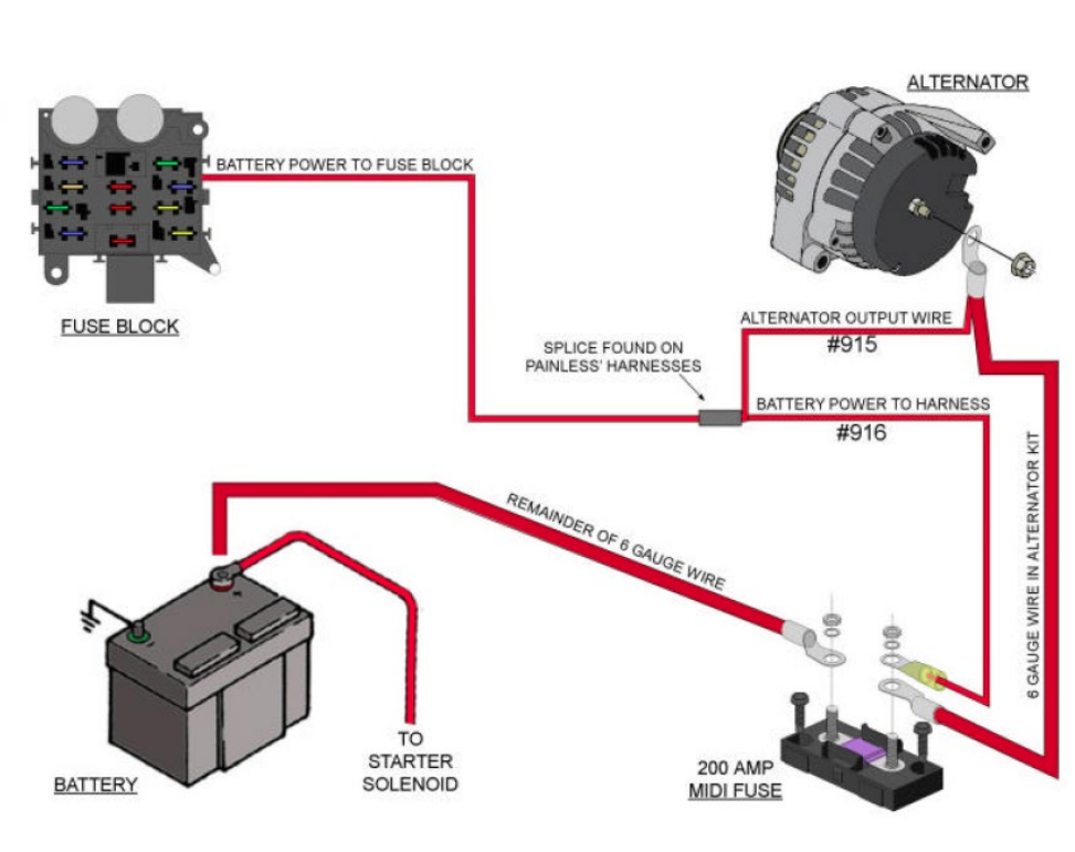
We have a detailed wiring diagram specifically illustrating the fusible link and its connections within a typical automotive electrical system. This diagram clearly shows the wiring colors, component locations, and circuit layout. You can download this valuable resource for free to aid in your diagnosis and repair efforts.