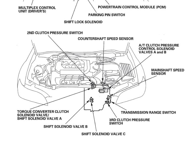
Diagram Honda Accord Shift Solenoid Location
Alright, let's talk shift solenoids in your Honda Accord. Specifically, understanding their location using a diagram. As an experienced DIYer, you know how crucial it is to pinpoint the exact location of a component before diving into any repair or modification. This article will equip you with the knowledge to effectively interpret shift solenoid diagrams, enabling you to diagnose transmission issues and perform necessary maintenance with confidence.
Purpose of a Shift Solenoid Diagram
Why bother with a diagram? Well, a shift solenoid diagram serves several crucial purposes:
- Repair and Maintenance: Accurately locating the solenoids is essential for replacing faulty units, checking wiring connections, and performing diagnostic tests.
- Troubleshooting: A diagram helps you trace circuits and identify potential problem areas when diagnosing transmission issues like hard shifting, slipping gears, or failure to shift altogether.
- Learning: Understanding the layout of the transmission's control system allows you to gain a deeper understanding of how it operates.
- Modification: If you're considering any modifications to the transmission, such as installing a shift kit or aftermarket solenoids, a diagram is indispensable for proper installation and avoiding damage.
Without a reliable diagram, you're essentially working blind, risking incorrect component removal or damage to surrounding parts. Trust me, knowing where things are before you start wrenching saves time, money, and frustration.
Key Specs and Main Parts
Before we delve into the diagram itself, let's review the key components and specifications you might encounter when dealing with Honda Accord shift solenoids.
Main Parts:
- Shift Solenoid Valves: These are electromechanical devices that control the flow of transmission fluid to various hydraulic circuits within the transmission. They are typically labeled as Solenoid A, Solenoid B, etc. Sometimes, you'll see them designated as a "Linear Solenoid Valve," meaning their output is proportional to the electrical current applied.
- Transmission Control Module (TCM) / Powertrain Control Module (PCM): The "brain" of the transmission. It receives inputs from various sensors (speed sensors, throttle position sensor, etc.) and uses this information to determine when to activate the shift solenoids. In newer Accords, the TCM is often integrated into the PCM.
- Wiring Harness: The network of wires that connects the TCM/PCM to the shift solenoids and other transmission components.
- Connectors: These provide the electrical connection between the wiring harness and the solenoids. Corrosion or loose connections can cause intermittent shifting problems.
- Transmission Fluid Passages: Internal channels within the transmission that carry hydraulic fluid to and from the solenoids.
Key Specs:
- Resistance Values: Each solenoid has a specific resistance range (measured in Ohms). This is a crucial specification for testing solenoid functionality with a multimeter. A value outside the specified range indicates a faulty solenoid. Typically, Honda solenoids have a resistance between 12-25 Ohms, but always refer to the specific repair manual for your Accord's year and transmission type.
- Voltage: Shift solenoids typically operate on 12V DC.
- Fluid Pressure: The hydraulic pressure controlled by the solenoids can vary depending on the gear and operating conditions. Pressure testing is a more advanced diagnostic procedure.
- Torque Specifications: When replacing solenoids, it’s essential to tighten the mounting bolts to the correct torque specification (usually in inch-pounds). Over-tightening can damage the solenoid or the transmission case.
Understanding Diagram Symbols
A shift solenoid diagram isn't just a picture; it's a symbolic representation of the electrical and hydraulic systems within the transmission. Let's decode some common symbols:
- Lines: Solid lines usually represent electrical wires. Dashed lines often indicate hydraulic lines or fluid passages. The thickness of the line may not be significant.
- Colors: Wire colors are crucial for tracing circuits. Common colors include red (power), black (ground), and various colors for signal wires. The diagram legend will always specify what each color represents.
- Solenoid Symbol: This typically looks like a rectangular box with a coil symbol inside, representing the solenoid's electromagnetic coil. It will be labeled (e.g., "Solenoid A").
- Ground Symbol: Usually represented by a series of horizontal lines decreasing in length, resembling an inverted pyramid.
- Connector Symbol: Depicts the electrical connector where the wiring harness plugs into the solenoid. You may see a numbered pinout diagram associated with the connector.
- TCM/PCM Symbol: Often depicted as a larger rectangular box with numerous pins, representing the inputs and outputs of the control module.
Pay close attention to the legend or key provided with the diagram. It's your guide to interpreting the symbols and understanding the diagram's conventions.
How It Works
Here's a simplified explanation of how the shift solenoids work in conjunction with the TCM/PCM:
- Driver Input and Sensor Data: The driver's actions (throttle position, gear selector position) and sensor data (vehicle speed, engine speed) are sent to the TCM/PCM.
- TCM/PCM Calculation: Based on this data, the TCM/PCM determines the optimal gear for the current driving conditions.
- Solenoid Activation: The TCM/PCM sends an electrical signal to the appropriate shift solenoids. This signal energizes the solenoid's coil, creating an electromagnetic field.
- Hydraulic Control: The electromagnetic field moves a valve within the solenoid, opening or closing fluid passages. This directs transmission fluid to the appropriate clutch packs or bands within the transmission.
- Gear Shift: The engagement or disengagement of these clutches and bands results in the desired gear shift.
The timing and sequencing of solenoid activation are critical for smooth and efficient shifting. Problems with the solenoids, wiring, or the TCM/PCM can disrupt this process, leading to shifting issues.
Real-World Use – Basic Troubleshooting Tips
Okay, diagram in hand, multimeter ready... let's troubleshoot:
- Check for Codes: Use an OBD-II scanner to retrieve diagnostic trouble codes (DTCs). Codes related to shift solenoids (e.g., P0750, P0755, P0760) provide valuable clues.
- Visual Inspection: Carefully inspect the wiring harness and connectors for any signs of damage, corrosion, or loose connections. Pay particular attention to the connectors at the solenoids themselves.
- Solenoid Resistance Test: Disconnect the solenoid connector and use a multimeter to measure the resistance across the solenoid terminals. Compare the measured value to the specification in the repair manual. An open circuit (infinite resistance) or a short circuit (very low resistance) indicates a faulty solenoid.
- Wiring Continuity Test: Use a multimeter to check the continuity of the wires between the TCM/PCM and the solenoids. A break in the wire will result in an open circuit.
- Power Supply Check: Verify that the solenoids are receiving the correct voltage (typically 12V) when activated. You may need a wiring diagram to identify the correct pins to test.
- Fluid Level and Condition: Low or contaminated transmission fluid can also cause shifting problems. Check the fluid level and condition and address any issues before proceeding with solenoid replacement.
Important Note: Before performing any electrical testing, always disconnect the negative battery cable to prevent accidental shorts or damage to the electrical system.
Safety – Highlight Risky Components
Working on a transmission involves several potential safety hazards. Keep these in mind:
- High Voltage: While the solenoids themselves operate on 12V, the electrical system in a vehicle can have higher voltages. Always disconnect the negative battery cable before working on any electrical components.
- Hot Surfaces: The transmission can get very hot, especially after driving. Allow the transmission to cool down completely before working on it to avoid burns.
- Sharp Edges: The transmission case and components can have sharp edges. Wear gloves to protect your hands.
- Heavy Components: The transmission itself is heavy and can be difficult to handle. Use proper lifting equipment and support it securely when removing or installing it.
- Transmission Fluid: Transmission fluid can be slippery and can irritate skin and eyes. Wear gloves and eye protection when handling it. Dispose of used transmission fluid properly according to local regulations.
- Potentially Risky Components: Be aware that if you are working on an automatic transmission, you are working with parts that, if damaged, can cause significant personal injury. If you are unfamiliar with working on transmissions, it is best to take your vehicle to a trusted, qualified mechanic.
Always prioritize safety and take necessary precautions to avoid injury.
You can download a detailed shift solenoid diagram specific to your Honda Accord's year and model. Knowing that you have this will significantly aid your troubleshooting and repair process. We have the file and can provide it to you upon request.