
Diagram Mass Air Flow Sensor Location
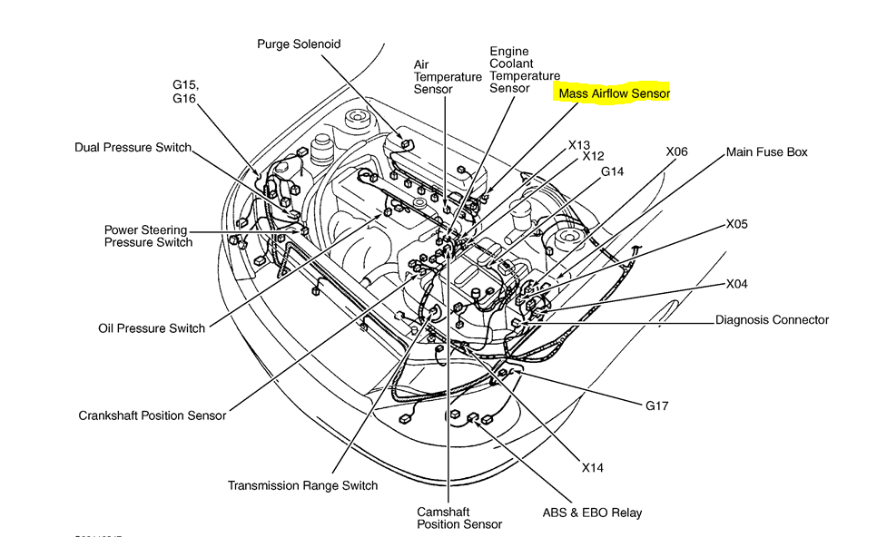
Let's dive into understanding the Mass Air Flow (MAF) sensor and, more specifically, how to locate it using a diagram. Whether you're tackling a pesky check engine light, planning performance modifications, or simply expanding your automotive knowledge, knowing where your MAF sensor resides and how it interacts with the engine is crucial. This guide will provide you with the necessary information to interpret MAF sensor location diagrams, understand their functionality, and even perform some basic troubleshooting.
Why Knowing the MAF Sensor Location Matters
A diagram showing the MAF sensor's location isn't just a pretty picture; it's a roadmap to essential engine diagnostics and maintenance. Understanding its placement empowers you to:
- Diagnose Engine Problems: The MAF sensor plays a critical role in engine performance. When it malfunctions, it can trigger the check engine light and cause symptoms like poor fuel economy, rough idling, or stalling. Locating it is the first step in diagnosing these issues.
- Perform Maintenance: Regular cleaning of the MAF sensor can improve engine performance and fuel economy. Knowing its location makes this preventative maintenance task much easier.
- Plan Modifications: If you're considering performance upgrades like a cold air intake, you'll need to know where the MAF sensor is located to integrate it properly with the new system.
- Understand Engine Layout: Familiarity with the MAF sensor's location contributes to a broader understanding of the engine's air intake system and overall layout.
Key Specs and Main Parts of a MAF Sensor
Before we dissect the diagrams, let's quickly review the anatomy of a typical MAF sensor and its relevant specifications:
Key Specs:
- Voltage Output: The MAF sensor outputs a voltage signal that varies depending on the amount of air flowing through it. This voltage is typically between 0 and 5 volts DC.
- Frequency Output (for some types): Some MAF sensors, particularly those used in newer vehicles, output a frequency signal instead of a voltage signal.
- Operating Temperature: MAF sensors are designed to operate within a specific temperature range. Extreme temperatures can affect their accuracy.
- Airflow Range: Each MAF sensor is designed to measure airflow within a specific range, measured in grams per second (g/s) or cubic feet per minute (CFM).
Main Parts:
- Sensor Housing: This is the outer casing of the MAF sensor, typically made of plastic or aluminum. It's designed to be inserted into the air intake system.
- Sensing Element: This is the heart of the MAF sensor, the component that actually measures the airflow. There are two primary types of sensing elements:
- Hot-Wire Anemometer: A thin wire or film is heated to a constant temperature. The amount of current required to maintain that temperature is proportional to the airflow.
- Hot-Film Anemometer: Similar to the hot-wire anemometer, but uses a thin film instead of a wire. Hot-film sensors are generally more durable and accurate.
- Electronic Circuitry: This circuitry processes the signal from the sensing element and converts it into a voltage or frequency output.
- Connector: The connector is used to connect the MAF sensor to the vehicle's wiring harness. It typically has 3 to 5 pins, depending on the sensor's design.
Understanding Symbols in MAF Sensor Location Diagrams
MAF sensor location diagrams often use standardized symbols to represent components and connections. Here's a breakdown of common symbols you might encounter:
- Solid Lines: Usually represent hoses or pipes that transport air. In the context of a MAF sensor, these will typically depict the intake ducting.
- Dotted Lines: Often indicate electrical wiring or vacuum lines. Pay attention to dotted lines connected to the MAF sensor; they lead to the engine control unit (ECU).
- Rectangles with "MAF" or similar labels: These clearly identify the MAF sensor itself. The diagram may specify the sensor type (e.g., "Hot-Wire MAF").
- Arrows: Show the direction of airflow through the intake system.
- Color Coding (if present): Although less common, some diagrams use colors to distinguish between different types of fluids or signals. A key should be provided to explain the color codes.
- ECU/PCM Symbol: A generic symbol for the Engine Control Unit or Powertrain Control Module, often a rectangle with pins representing the wiring connections.
It's essential to cross-reference the diagram's legend or key to understand the meaning of each symbol. Always refer to the specific diagram for your vehicle model, as symbols can vary slightly.
How the MAF Sensor Works: A Technical Overview
The MAF sensor's job is to measure the mass of air entering the engine. This information is critical for the ECU to calculate the correct amount of fuel to inject, ensuring optimal combustion. Here's a simplified explanation:
- Air enters the engine through the air filter and flows through the intake ducting.
- The air passes over the MAF sensor's sensing element (hot-wire or hot-film).
- The sensing element is heated to a constant temperature. As air flows past it, it cools down.
- The MAF sensor's circuitry measures the amount of current or power required to maintain the sensing element's temperature.
- The more air flowing through, the more current is needed to keep the element hot. This current is directly proportional to the mass of the air.
- The MAF sensor converts this measurement into a voltage or frequency signal that is sent to the ECU.
- The ECU uses this signal, along with other sensor inputs (e.g., throttle position, engine speed), to calculate the optimal fuel injection amount.
Real-World Use: Basic Troubleshooting Tips
Here are a few practical troubleshooting tips related to the MAF sensor, assuming you've located it using the diagram:
- Visual Inspection: Check the MAF sensor for any obvious damage, such as cracks in the housing or corrosion on the connector. Ensure the connector is securely attached.
- Cleaning: A dirty MAF sensor can provide inaccurate readings. Use a specialized MAF sensor cleaner (available at auto parts stores) to gently clean the sensing element. Do not use carb cleaner or other harsh solvents, as they can damage the sensor.
- Voltage Testing: With the engine running (or key in the "on" position, consult your repair manual), use a multimeter to check the voltage output of the MAF sensor. Compare the reading to the expected range specified in your vehicle's repair manual.
- Wiring Check: Inspect the wiring harness leading to the MAF sensor for any signs of damage, such as frayed wires or loose connections. Use a wiring diagram (often included with the MAF location diagram) to verify the correct pinout.
- Scan Tool Data: Use an OBD-II scan tool to monitor the MAF sensor readings in real-time. Look for any erratic or inconsistent values.
Important: Always consult your vehicle's repair manual for specific troubleshooting procedures and diagnostic codes related to the MAF sensor. Generic advice can be misleading.
Safety Considerations
Working on your vehicle's electrical system involves certain safety risks. Keep these points in mind when dealing with the MAF sensor:
- Disconnect the Battery: Before working on any electrical components, disconnect the negative battery terminal to prevent accidental shorts.
- Handle with Care: The sensing element of the MAF sensor is fragile. Avoid touching it directly or using excessive force when cleaning it.
- Use Proper Tools: Use the correct tools for the job, such as a multimeter and a MAF sensor cleaner.
- Be Aware of Hot Surfaces: The engine compartment can contain hot surfaces. Allow the engine to cool down before working on the MAF sensor.
- Avoid Static Electricity: Static electricity can damage the MAF sensor's electronic components. Ground yourself before touching the sensor.
The MAF sensor's electrical connector and wiring can be a shock hazard if mishandled while the engine is running. Always disconnect power before disconnecting the sensor.
Understanding the MAF sensor's location and function is a valuable asset for any DIY mechanic. By carefully studying the diagrams and following the troubleshooting tips outlined above, you can effectively diagnose and resolve MAF sensor-related issues. We have a file containing various MAF sensor diagrams that may be useful for you. Please contact us to download the relevant diagram for your vehicle. Happy wrenching!