Diagram Nissan Altima Oxygen Sensor Location
So, you're diving into the oxygen sensor system on your Nissan Altima? Excellent! This article is your roadmap to understanding the oxygen sensor locations and how they function within your car's engine management system. Having a good understanding of this system is crucial for efficient troubleshooting, performance modifications, or even just understanding why your check engine light is on. Consider this your expert guide, designed to help even experienced DIYers navigate the complexities with confidence.
Why This Diagram Matters
Let's cut to the chase: a clear understanding of your Altima's oxygen sensor layout is vital for several reasons:
- Repair and Replacement: Knowing exactly where each sensor is located saves you time and prevents accidental damage to other components. It's far more efficient to target the specific sensor causing an issue than to blindly poke around.
- Performance Tuning: For those looking to enhance their Altima's performance, understanding how the oxygen sensors contribute to the air/fuel ratio is essential. Modifications without this knowledge can lead to suboptimal results or even engine damage.
- Diagnostic Accuracy: When the dreaded check engine light illuminates, a diagnostic trouble code (DTC) related to an oxygen sensor is common. Knowing the sensor locations, and which sensor the code refers to, is half the battle in fixing the problem.
- Understanding Engine Management: Even if you're not planning any immediate repairs, grasping the role and placement of these sensors provides a deeper insight into how your engine control unit (ECU) manages the combustion process.
Key Specs and Main Parts
Before we get into the diagram itself, let's establish some core knowledge about the Altima's oxygen sensor system. The number and type of oxygen sensors can vary slightly depending on the engine (e.g., 2.5L inline-4 or 3.5L V6) and model year, but the general principles remain the same.
Types of Oxygen Sensors
- Upstream (Pre-Catalytic Converter) Sensors: These sensors, also known as air-fuel ratio sensors (especially in newer models), are located *before* the catalytic converter in the exhaust stream. Their primary job is to measure the oxygen content of the exhaust gas *immediately* after combustion. This information is crucial for the ECU to fine-tune the air/fuel mixture entering the engine. These sensors are typically wideband sensors, providing a more precise reading than older narrowband sensors.
- Downstream (Post-Catalytic Converter) Sensors: Located *after* the catalytic converter, these sensors monitor the efficiency of the converter. They compare the oxygen levels before and after the converter. A properly functioning converter will significantly reduce the oxygen content downstream.
Main Components
- Oxygen Sensor Body: This contains the sensing element, typically made of zirconia or titania.
- Sensor Connector: Connects the sensor to the vehicle's wiring harness, transmitting the oxygen level signal to the ECU.
- Heating Element (in Heated Oxygen Sensors - HO2S): Most modern oxygen sensors are heated to reach their operating temperature quickly, improving accuracy and reducing emissions, especially during cold starts. The heating element is powered by the vehicle's electrical system.
- Exhaust Manifold/Piping: This is where the oxygen sensors are physically mounted.
- Catalytic Converter: While not part of the sensor itself, the catalytic converter's performance is monitored by the downstream oxygen sensor.
Symbols and Diagram Conventions
A good diagram will use standardized symbols to represent different components and connections. Here's what you can expect to see in an Altima oxygen sensor location diagram:
- Oxygen Sensor Symbol: Typically depicted as a rounded or rectangular shape with a wire extending from it. Sometimes the letter "O2" is included.
- Wiring: Solid lines represent electrical wires connecting the sensors to the ECU and other components.
- Connector Symbol: Connectors are usually shown as interlocking shapes or a small rectangle with pins.
- Engine Block: A simplified representation of the engine block will provide spatial context.
- Exhaust Manifold/Piping: Usually depicted as lines or pipes running from the engine block.
- Catalytic Converter: Shown as a larger cylindrical or rectangular shape within the exhaust system.
- Sensor Labeling: Labels like "Sensor 1," "Sensor 2," "Bank 1," and "Bank 2" are crucial for identifying specific sensors. Bank 1 typically refers to the side of the engine containing cylinder #1 (in V6 engines). Sensor 1 always refers to the upstream sensor, and Sensor 2 refers to the downstream sensor.
Colors may be used in some diagrams to differentiate wiring or to indicate the type of signal being transmitted. However, black and white diagrams are also common, relying on labeling and line styles.
How It Works
The oxygen sensor is essentially a miniature generator. It produces a voltage based on the difference in oxygen concentration between the exhaust gas and the ambient air outside the sensor. The sensing element reacts with the exhaust gases, and this reaction generates a voltage signal. The higher the oxygen concentration in the exhaust (leaner mixture), the lower the voltage produced. Conversely, a lower oxygen concentration (richer mixture) results in a higher voltage.
The ECU uses this voltage signal from the upstream sensors to adjust the fuel injectors, ensuring the optimal air/fuel ratio (ideally, stoichiometric - about 14.7:1). This closed-loop feedback system constantly adjusts the fuel mixture for optimal combustion efficiency and reduced emissions.
The downstream sensor, as mentioned earlier, monitors the catalytic converter's performance. It should show a relatively stable voltage reading, indicating that the converter is effectively oxidizing pollutants. If the downstream sensor voltage fluctuates significantly, it could indicate a failing catalytic converter.
Real-World Use: Basic Troubleshooting Tips
Here are some common problems related to oxygen sensors and how to address them:
- Check Engine Light (CEL) with Oxygen Sensor DTC: Use an OBD-II scanner to retrieve the diagnostic trouble code (DTC). Common codes include P0131, P0134, P0137, P0140, P0171, P0174, and many others. The code will indicate which sensor is malfunctioning. Consult your Altima's repair manual or online resources to interpret the specific code.
- Poor Fuel Economy: A failing upstream oxygen sensor can cause the ECU to miscalculate the air/fuel ratio, leading to excessive fuel consumption.
- Rough Idling or Stalling: An inaccurate oxygen sensor signal can disrupt the engine's idle control, resulting in rough idling or even stalling.
- Failed Emissions Test: Malfunctioning oxygen sensors can lead to increased emissions, causing your vehicle to fail an emissions test.
Troubleshooting Steps:
- Visual Inspection: Check the oxygen sensor for any obvious damage, such as cracked housing or damaged wiring.
- Wiring and Connectors: Ensure that the wiring harness and connectors are clean, secure, and free from corrosion. Use a multimeter to check for continuity and proper voltage at the sensor connector.
- Sensor Resistance Test: Use a multimeter to measure the resistance of the sensor's heating element (if applicable). Compare the reading to the specifications in your Altima's repair manual.
- Sensor Voltage Test: Use a multimeter to monitor the sensor's voltage output while the engine is running. Observe how the voltage changes as you vary the engine's RPM.
- Scan Tool Data Monitoring: Use an OBD-II scanner that displays live data to monitor the oxygen sensor readings in real-time. This can help you identify erratic or out-of-range sensor values.
Safety Considerations
Working on the exhaust system carries several risks:
- Hot Exhaust: The exhaust system gets incredibly hot. Always allow the engine to cool completely before working on any exhaust components. Use heat-resistant gloves.
- Corrosion and Rust: Exhaust components are prone to corrosion and rust, making them difficult to remove. Use penetrating oil and appropriate tools to avoid damaging the components.
- Electrical Hazards: When working with the oxygen sensor wiring, disconnect the negative battery terminal to prevent electrical shocks. Be careful not to short-circuit any wires.
- Exhaust Fumes: Work in a well-ventilated area to avoid inhaling harmful exhaust fumes.
- Catalytic converters contain platinum and other precious metals and are a target for theft. When replacing, dispose of the old catalytic converter responsibly.
Always wear safety glasses and gloves when working on your vehicle.
You're now armed with a solid understanding of the Nissan Altima oxygen sensor system. Remember to consult your Altima's repair manual for specific procedures and specifications. Good luck with your diagnosis and repairs!
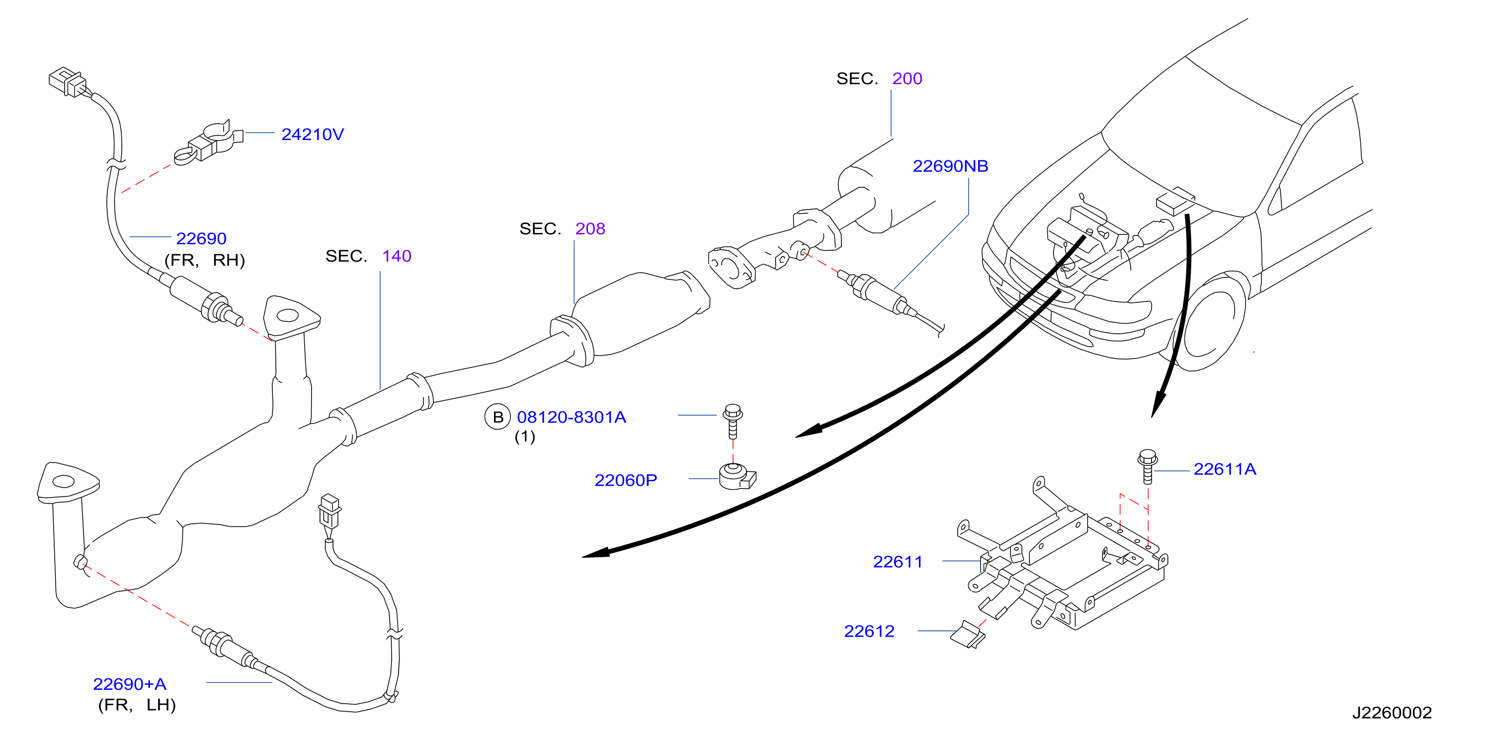
We have a detailed diagram of the Nissan Altima oxygen sensor locations available for download. This diagram provides a clear visual representation of the sensor locations, wiring, and other key components. Contact us for access to the file to aid your repairs.