
Diagram Nissan Rear Drum Brake Repair
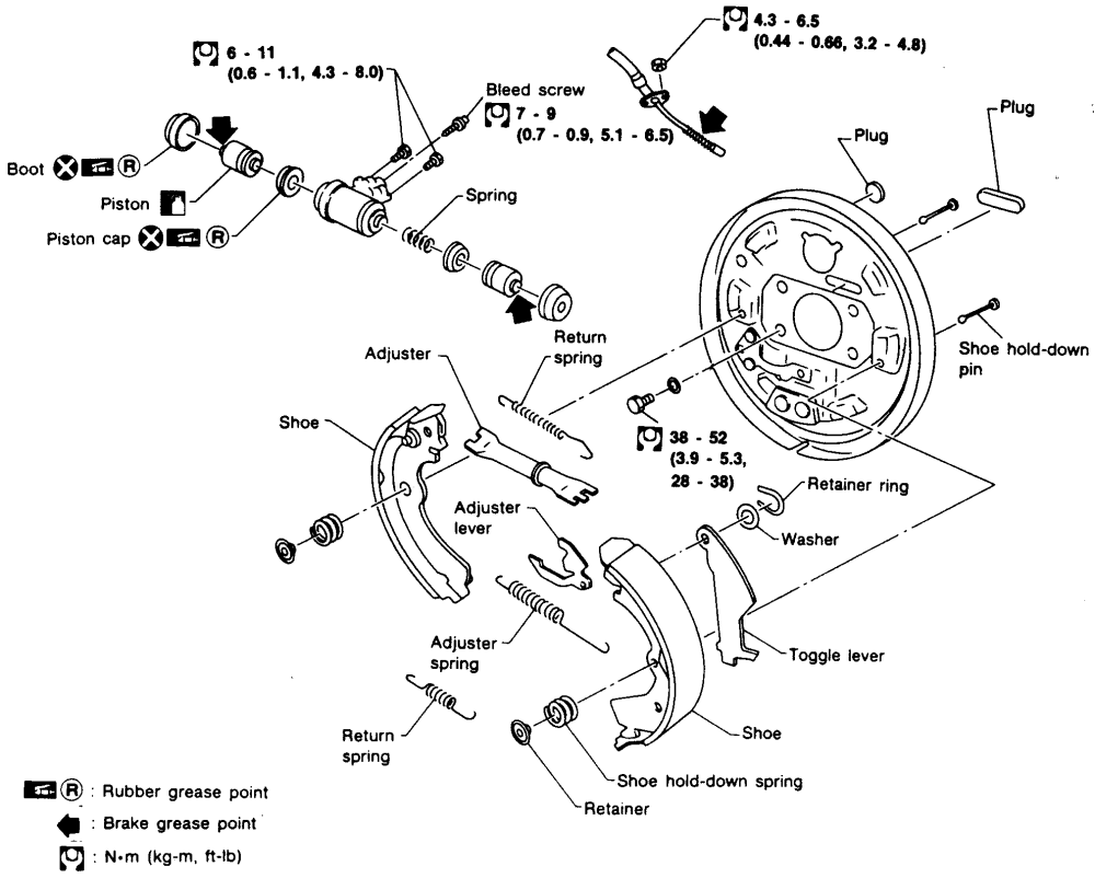
Rear drum brakes, while increasingly less common in modern vehicles, are still a staple on many cars and trucks, especially older models and some smaller vehicles. Understanding how they work and being able to diagnose and repair them is a valuable skill for any DIY mechanic. This article serves as a guide to understanding a typical Nissan rear drum brake diagram, enabling you to confidently tackle repairs and maintenance.
Purpose of the Diagram
A rear drum brake diagram is a technical illustration showing the layout and components of the drum brake assembly. It's crucial for several reasons:
- Repair and Maintenance: The primary use is guiding repair work. It helps you identify parts, understand their relationships, and reassemble everything correctly after disassembly.
- Troubleshooting: The diagram helps in pinpointing the source of brake problems by illustrating the location of various components.
- Parts Identification: A detailed diagram allows you to accurately identify and order the correct replacement parts.
- Learning and Understanding: Even if you don't plan on immediate repairs, studying the diagram provides a deeper understanding of how drum brakes function, which is beneficial for general automotive knowledge.
- Modification and Upgrades: If you're considering upgrading your braking system, understanding the existing setup is vital.
Key Specs and Main Parts
A typical Nissan rear drum brake assembly diagram will show the following key components. Note that slight variations may exist depending on the specific model year and trim.
- Brake Drum: The large, rotating metal cylinder that the brake shoes press against to create friction and stop the vehicle. The inside surface of the drum is the friction surface.
- Brake Shoes: Two curved friction material-lined components that are pressed against the inside of the drum. They are the primary wear items in the system. Usually one is the primary shoe (facing the front of the vehicle) and the other is the secondary shoe (facing the rear).
- Wheel Cylinder: A hydraulic cylinder located at the top of the brake assembly. When you press the brake pedal, hydraulic pressure forces pistons in the wheel cylinder outwards, pushing the brake shoes against the drum.
- Return Springs: These springs pull the brake shoes back away from the drum when the brake pedal is released. There are usually two: an upper and a lower spring.
- Adjuster Assembly: A mechanism (often star-wheel shaped) that compensates for brake shoe wear. As the shoes wear down, the adjuster automatically extends to maintain proper shoe-to-drum clearance. Nissan frequently uses a self-adjusting mechanism.
- Hold-Down Springs: Small springs with pins and retainers that hold the brake shoes securely against the backing plate.
- Parking Brake Lever and Strut: A lever attached to one of the brake shoes that is actuated by the parking brake cable. The strut connects the lever to the other shoe. When the parking brake is engaged, the lever pivots, forcing the strut to push the other shoe against the drum.
- Backing Plate: The stationary metal plate to which all the brake components are mounted.
- Brake Lines: Metal lines that carry hydraulic fluid from the master cylinder to the wheel cylinders.
- Bleeder Screw: Located on the wheel cylinder. Used to remove air from the hydraulic brake system.
Symbols and Conventions
Understanding the symbols used in the diagram is crucial for interpreting it correctly.
- Solid Lines: Generally represent the physical outline of a component. Thicker lines often indicate a major component or the boundary of the assembly.
- Dashed Lines: May indicate hidden parts or internal features. They can also be used to show the path of movement of a component.
- Arrows: Indicate the direction of movement or force. For example, arrows on the wheel cylinder pistons show the direction they move when the brakes are applied.
- Section Views: Some diagrams may include section views, which show a cutaway of the assembly to reveal internal details. These are usually indicated by a dashed line with a cutting plane symbol.
- Component Numbers: Each part is typically labeled with a number that corresponds to a parts list or legend included with the diagram.
- Torque Specifications: Important bolts and fasteners may be labeled with their torque specifications (e.g., "25 Nm" or "18 ft-lb"). Always use a torque wrench to tighten fasteners to the specified torque.
- Color Coding: While not always present, some diagrams may use color to differentiate between different types of components or systems. For example, hydraulic lines may be colored blue, and electrical components may be colored yellow.
How It Works
The Nissan rear drum brake system operates on the principle of friction. Here's a simplified breakdown:
- When you press the brake pedal, the master cylinder (located under the hood) sends hydraulic fluid under pressure through the brake lines to the wheel cylinders at each rear wheel.
- The hydraulic pressure in the wheel cylinder forces the pistons outward.
- The pistons push the brake shoes against the inside surface of the rotating brake drum.
- The friction between the brake shoes and the drum slows down the drum's rotation, which in turn slows down the wheel and the vehicle.
- When you release the brake pedal, the hydraulic pressure is released.
- The return springs pull the brake shoes back away from the drum, allowing the wheel to rotate freely again.
- As the brake shoes wear, the self-adjusting mechanism (if equipped) will extend the adjuster to maintain the proper shoe-to-drum clearance. This ensures that the brakes continue to function effectively even as the friction material wears down.
Real-World Use and Troubleshooting Tips
Here are some common issues you might encounter and how the diagram can help you diagnose them:
- Spongy Brake Pedal: Often caused by air in the brake lines. The diagram shows the location of the bleeder screw on the wheel cylinder, which is used to bleed the air out of the system.
- Brake Squealing or Grinding: Could indicate worn brake shoes, a worn brake drum, or contaminated friction surfaces. The diagram helps you inspect the shoes for wear and the drum for damage.
- Uneven Braking: Can be caused by a malfunctioning wheel cylinder, contaminated brake shoes, or an improperly adjusted brake assembly. The diagram helps you isolate the affected components.
- Parking Brake Not Holding: Might be due to a stretched or broken parking brake cable, or an improperly adjusted parking brake mechanism within the drum brake assembly. The diagram helps you inspect the parking brake lever, strut, and cable.
- Brake Drag: Occurs when the brake shoes don't fully retract from the drum. This can be caused by sticking wheel cylinder pistons, weak return springs, or an improperly adjusted brake assembly. The diagram can help you locate and inspect these components.
- Brake Fluid Leak: Inspect the wheel cylinder and brake lines based on the diagram.
Safety Considerations
Working on brake systems involves inherent risks. Pay close attention to the following:
- Brake Fluid: Brake fluid is corrosive and can damage paint. Clean up any spills immediately. Wear eye protection and gloves.
- Asbestos: Older brake shoes may contain asbestos. Avoid creating dust when handling them. Wear a respirator and dispose of the old shoes properly according to local regulations. Modern brake shoes generally don't contain asbestos, but always err on the side of caution.
- Brake Dust: Brake dust can be harmful to your lungs. Wear a respirator when working on brakes.
- Springs: Brake return springs are under tension and can be dangerous if released improperly. Use the correct brake spring tools to remove and install them safely.
- Wheel Cylinder: The wheel cylinder contains pressurized brake fluid. Be careful when disassembling it.
- Jack Stands: Never work under a vehicle supported only by a jack. Use properly rated jack stands.
- Cleanliness: Keep all brake components clean. Contamination can significantly reduce brake performance.
- Proper Torque: Always tighten fasteners to the specified torque using a torque wrench. Over-tightening can damage components, and under-tightening can lead to brake failure.
By understanding the diagram and following safe practices, you can confidently perform repairs and maintenance on your Nissan's rear drum brakes. Remember to consult your vehicle's service manual for specific instructions and torque specifications.
We have the Nissan rear drum brake diagram file available for you to download. It provides a detailed visual representation of the system, making your repair and maintenance tasks easier and more efficient.