
Diagram Of A Car Air Conditioning System
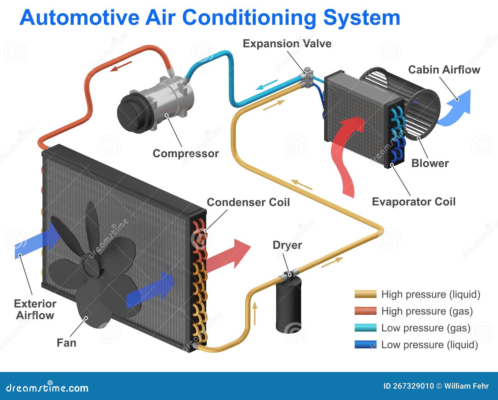
Let's dive into the heart of your car's comfort system – the air conditioning (A/C). This article provides a comprehensive look at a typical car A/C system diagram, breaking down its components, functions, and how to interpret the symbols. Understanding this diagram is invaluable for troubleshooting, performing basic maintenance, or even considering modifications to your A/C setup. Forget sweating through summer – let's get technically cool!
Purpose of Understanding the A/C Diagram
Why bother with a diagram? Well, a good A/C system diagram is your roadmap to understanding how the entire system works. It's essential for:
- Troubleshooting: When your A/C isn't blowing cold, the diagram helps you trace the refrigerant flow and pinpoint potential problem areas.
- Maintenance: Identifying components and their locations makes tasks like filter replacement or visual inspections much easier.
- DIY Repairs: Replacing a faulty component like a pressure switch or a compressor becomes less daunting when you understand its place in the system.
- Modifications: Planning upgrades, such as adding an auxiliary cooler or converting to a different refrigerant, requires a solid understanding of the existing setup.
- General Knowledge: Simply understanding how the A/C system works allows you to better understand the overall function of your vehicle.
Having a diagram at your disposal is like having a trusted mechanic whispering in your ear – guiding you through the complexities of your car's cooling system. And guess what? We have a detailed diagram file ready for you to download and use. More on that later!
Key Specs and Main Parts
A typical car A/C system operates on a closed-loop refrigerant cycle. The main components involved are:
- Compressor: The heart of the system. The compressor is a pump driven by the engine that compresses the refrigerant gas, increasing its pressure and temperature.
- Condenser: Located at the front of the car, often near the radiator. The condenser dissipates heat from the high-pressure, high-temperature refrigerant gas, causing it to condense into a high-pressure liquid.
- Receiver-Drier (or Accumulator): This component acts as a filter and a storage reservoir for the refrigerant. It removes moisture and contaminants from the refrigerant, protecting the system from damage. The receiver-drier is typically found in systems with a thermal expansion valve (TXV), while the accumulator is used in systems with an orifice tube.
- Thermal Expansion Valve (TXV) or Orifice Tube: These are metering devices that control the flow of refrigerant into the evaporator. The TXV is a more sophisticated valve that adjusts the refrigerant flow based on the evaporator temperature, providing more efficient cooling. The orifice tube is a simpler, fixed-size restrictor.
- Evaporator: Located inside the dashboard, the evaporator absorbs heat from the cabin air, causing the liquid refrigerant to evaporate into a low-pressure gas. This process cools the air that is blown into the cabin.
- Refrigerant: The working fluid of the system. Common refrigerants include R-134a and, increasingly, R-1234yf.
- Pressure Switches: These switches monitor the refrigerant pressure and protect the system from damage. Low-pressure switches prevent the compressor from running when the refrigerant level is too low, while high-pressure switches shut down the compressor if the pressure becomes excessively high.
- Blower Motor: Forces air across the evaporator core, delivering the cooled air into the cabin.
Symbols and Conventions in A/C Diagrams
Understanding the symbols used in A/C diagrams is crucial for interpreting them correctly. Here are some common conventions:
- Lines:
- Solid lines: Usually represent refrigerant lines. Different line thicknesses may indicate different pipe diameters.
- Dotted lines: Often indicate control lines or vacuum lines.
- Dashed lines: Can represent electrical wiring.
- Colors: Color coding can vary depending on the diagram, but some common associations are:
- Blue: Low-pressure refrigerant side.
- Red: High-pressure refrigerant side.
- Green: Might represent a specific type of control line or sensor signal.
- Icons: Specific icons represent each component. These icons are standardized across many diagrams. You'll typically see schematic representations of the compressor, condenser, evaporator, and other components. Look for a legend on the diagram that explains the symbols used.
How the A/C System Works
Let's walk through the refrigerant cycle step-by-step:
- Compression: The compressor draws in low-pressure, low-temperature refrigerant gas and compresses it, increasing its pressure and temperature.
- Condensation: The hot, high-pressure refrigerant gas flows to the condenser, where it dissipates heat to the surrounding air. This causes the refrigerant to condense into a high-pressure liquid.
- Metering: The high-pressure liquid refrigerant flows to the receiver-drier (or accumulator) for filtering and storage. From there, it passes through the TXV (or orifice tube), which reduces the pressure of the refrigerant and meters its flow into the evaporator.
- Evaporation: The low-pressure, low-temperature refrigerant liquid enters the evaporator. As air from the cabin is blown across the evaporator core by the blower motor, the refrigerant absorbs heat, causing it to evaporate into a low-pressure gas. This process cools the air.
- Return: The low-pressure refrigerant gas flows back to the compressor, completing the cycle.
Real-World Use: Basic Troubleshooting Tips
Using your diagram, you can perform some basic troubleshooting:
- No Cold Air: Check the compressor clutch is engaging when the A/C is turned on. If not, investigate the compressor, pressure switches, and electrical connections. The diagram will show you the wiring path to the compressor.
- Weak Airflow: Inspect the cabin air filter and blower motor. The diagram will show the location of the blower motor and its wiring.
- Cycling On and Off: Could indicate low refrigerant. Use the diagram to locate the low-pressure service port and have a qualified technician check the refrigerant level.
- Leaks: Look for visual signs of refrigerant leaks (oily residue) around fittings and connections. The diagram helps you identify all the potential leak points.
Important Note: Refrigerant leaks require professional attention. Releasing refrigerant into the atmosphere is illegal and harmful to the environment.
Safety Precautions
Working on an A/C system involves handling pressurized refrigerant, which can be dangerous. Always take the following precautions:
- Refrigerant is hazardous. Never release refrigerant into the atmosphere. Always recover refrigerant using proper equipment.
- High pressure. The high-pressure side of the system can reach very high pressures, potentially causing injury if a line ruptures.
- Electrical components. Be cautious when working around electrical components, such as the compressor clutch and pressure switches. Disconnect the battery before working on electrical circuits.
- Wear safety glasses and gloves. Protect your eyes and skin from contact with refrigerant.
- Consult a qualified technician. If you are not comfortable working on the A/C system, seek professional help.
The compressor is a particularly risky component due to the high pressures involved. Improper handling can lead to serious injury. Always relieve pressure before disconnecting any lines.
Remember to consult your vehicle's service manual for specific instructions and safety guidelines.
Now that you understand the anatomy of your car's A/C system, you're well-equipped to diagnose issues and potentially perform minor repairs. Remember to prioritize safety and consult a qualified technician when dealing with complex or potentially hazardous situations.
As promised, we have a detailed A/C system diagram file ready for you to download. It provides a visual representation of the system, complete with labeled components and refrigerant flow paths. To access the diagram, simply [Insert Link Here - Placeholder]. Good luck, and stay cool!