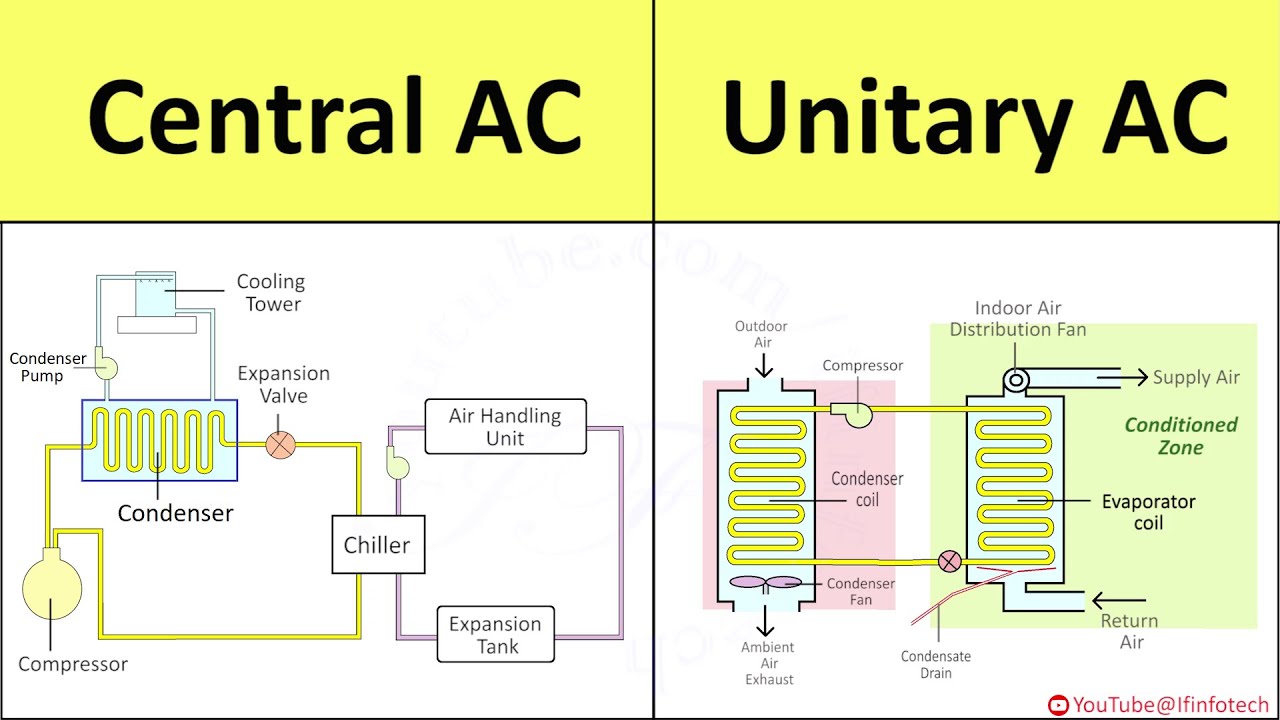
Diagram Of A Central Air Conditioning System
Let's dive into the inner workings of a central air conditioning system. Understanding its anatomy is invaluable whether you're planning a repair, upgrading your existing system, or simply want to learn more about how this crucial piece of home comfort operates. This article provides a detailed breakdown, assuming you have some mechanical aptitude and are comfortable with basic tools and safety procedures. Consider this your guide to deciphering a central AC system diagram.
Purpose of the Diagram
A central air conditioning system diagram is more than just a pretty picture; it's a roadmap. It serves several crucial purposes:
- Troubleshooting: When your AC malfunctions, the diagram helps pinpoint the source of the problem by illustrating the system's components and their relationships.
- Repair: Whether you're replacing a capacitor or an entire compressor, the diagram guides you through the disassembly and reassembly process.
- Learning: For the DIY enthusiast, the diagram provides a visual representation of the AC system, facilitating a deeper understanding of its operating principles.
- System Optimization: Understanding the diagram allows for informed decisions regarding system upgrades or modifications to improve efficiency.
By using a diagram, you can methodically approach diagnostics and repairs, saving time and potentially avoiding costly professional service calls.
Key Specs and Main Parts
Before we dissect the diagram, let's define the major players in a central AC system:
- Compressor: The heart of the system. It pressurizes the refrigerant, raising its temperature. Think of it as the pump that circulates the refrigerant.
- Condenser Coil: Located outside, it releases heat from the refrigerant as it changes from a high-pressure gas to a high-pressure liquid. A fan helps dissipate the heat.
- Expansion Valve (or Metering Device): This controls the flow of refrigerant into the evaporator coil, reducing the pressure and temperature. This pressure drop is key to the cooling process. Some systems use a thermal expansion valve (TXV), while others use a fixed orifice.
- Evaporator Coil: Located inside your air handler, this is where the refrigerant absorbs heat from the indoor air, causing it to evaporate from a low-pressure liquid to a low-pressure gas. A blower fan then circulates the cooled air through your ductwork.
- Refrigerant Lines: Copper pipes that carry the refrigerant between the components. These consist of the liquid line (high-pressure liquid refrigerant) and the suction line (low-pressure gas refrigerant).
- Air Handler: The indoor unit containing the evaporator coil, blower fan, and sometimes electric heating elements.
- Thermostat: The control center. It senses the room temperature and signals the system to turn on or off.
- Filter Drier: A small component in the liquid line that removes moisture and contaminants from the refrigerant. Essential for system longevity.
- Accumulator (or Suction Line Accumulator): Installed in the suction line, it prevents liquid refrigerant from entering the compressor, which could cause catastrophic damage.
- Capacitors: Electrical components that provide a jolt of energy to start the compressor and fan motors.
Symbols – Decoding the Diagram
AC diagrams use a standardized set of symbols to represent components and connections. Here’s a key to understanding the common symbols:
- Solid Lines: Usually represent refrigerant lines. Thicker lines might indicate larger diameter pipes or higher pressure.
- Dashed Lines: Often represent electrical wiring or control signals.
- Compressor Symbol: Typically a circle with a 'C' inside or a stylized representation of a pump.
- Condenser/Evaporator Coil Symbol: Represented as a series of zigzag lines or interconnected loops.
- Expansion Valve Symbol: Often shown as a triangle pointing into a diamond shape.
- Filter Drier Symbol: A small rectangle with a filter symbol inside.
- Thermostat Symbol: Can vary, but often includes a temperature scale and control knobs.
- Electrical Symbols: Resistors, capacitors, motors, switches – standard electrical symbols apply. Familiarize yourself with these basic electrical schematic symbols.
Colors on diagrams can also be informative. For example:
- Red: High-pressure refrigerant lines or hot electrical wires.
- Blue: Low-pressure refrigerant lines or neutral electrical wires.
Always refer to the legend on the specific diagram you're using, as symbol conventions can vary slightly between manufacturers.
How It Works: The Refrigeration Cycle
The central AC system operates on the principle of the refrigeration cycle. Here’s a simplified explanation, following the refrigerant's journey:
- Compression: The compressor takes in low-pressure, low-temperature refrigerant gas and compresses it, increasing its pressure and temperature significantly.
- Condensation: The hot, high-pressure refrigerant gas flows to the condenser coil, where it releases heat to the outside air. As it loses heat, it changes state from a gas to a high-pressure, high-temperature liquid.
- Expansion: The high-pressure, high-temperature liquid refrigerant flows through the expansion valve (or metering device). This reduces the pressure and temperature of the refrigerant drastically.
- Evaporation: The cold, low-pressure refrigerant liquid flows to the evaporator coil inside the air handler. Here, it absorbs heat from the warm indoor air, causing it to evaporate and change back into a low-pressure, low-temperature gas. This process cools the air, which is then circulated through your home.
- Back to the Compressor: The low-pressure, low-temperature refrigerant gas returns to the compressor, and the cycle repeats.
The efficiency of this cycle is measured by the Seasonal Energy Efficiency Ratio (SEER). A higher SEER rating indicates a more efficient system.
Real-World Use: Basic Troubleshooting Tips
Using the diagram can help you with basic troubleshooting:
- AC Not Cooling: Check the compressor. Is it running? If not, check the capacitor. A faulty capacitor is a common culprit. Also, ensure the condenser fan is running. A dirty condenser coil restricts airflow and reduces efficiency.
- AC Freezing Up: This could be due to low refrigerant charge (a leak somewhere in the system) or restricted airflow across the evaporator coil (dirty filter). The diagram will help you locate the evaporator coil and trace the refrigerant lines.
- No Power: Start with the thermostat and circuit breaker. Trace the wiring using the diagram to identify any potential breaks or loose connections.
- Unusual Noises: The diagram can help you identify the location of different components. Noises coming from the compressor might indicate a serious problem, while noises from the blower fan could be due to a loose or unbalanced fan blade.
Remember: These are just basic troubleshooting steps. Complex issues require specialized knowledge and equipment.
Safety First!
Working on an AC system involves potential hazards:
- High Voltage: Capacitors can store a dangerous electrical charge even when the system is off. Always discharge capacitors before handling them.
- Refrigerant: Refrigerant can cause frostbite if it comes into contact with your skin. It's also harmful to the environment. Properly recover refrigerant if you need to open the system. This requires specialized equipment.
- Moving Parts: The compressor, condenser fan, and blower fan have moving parts that can cause injury. Disconnect power before working near these components.
If you're not comfortable working with electrical components or refrigerant, consult a qualified HVAC technician. Your safety is paramount.
We have a detailed central AC system diagram available for download. This diagram includes detailed labeling and component callouts to aid in your understanding and troubleshooting efforts.