Diagram Of An Automatic Transmission
Alright, let's dive into the inner workings of an automatic transmission. This isn't just about knowing the names of parts; understanding how it all works is key, whether you're planning a fluid change, diagnosing a problem, or even considering a performance upgrade. Having a clear diagram is invaluable, and we've got a detailed one ready for you to download (link at the end). This article will break down that diagram and empower you to understand your automatic transmission like never before.
Purpose of Understanding the Automatic Transmission Diagram
Why bother with this diagram? Simple. Automatic transmissions are complex beasts. A good diagram serves several crucial purposes:
- Diagnosis: When your car's shifting is acting up, the diagram can help you trace the problem. Is it a valve body issue? A solenoid malfunction? The diagram will point you in the right direction.
- Repair: If you're brave enough to tackle repairs yourself (and some are certainly doable), a diagram is essential for reassembly and understanding the relationship between parts.
- Modification: Planning a shift kit installation or torque converter upgrade? Understanding the transmission's layout is paramount for proper installation and tuning.
- Knowledge: Even if you're not wrenching, knowing how your transmission functions can help you better understand your vehicle's overall operation and driving characteristics.
Key Specs and Main Parts
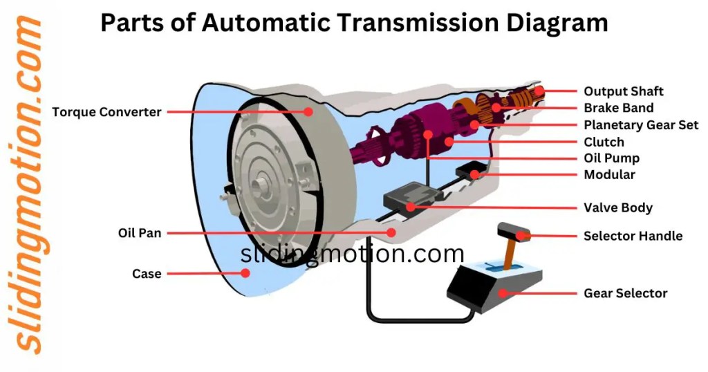
Automatic transmissions manage torque and speed differently from manual transmissions. Instead of gears you manually select, automatics use a system of planetary gearsets, clutches, bands, and hydraulic control to seamlessly shift between gears. Here are some key components, which you'll find clearly labelled on the downloadable diagram:
- Torque Converter: This is your link to the engine. It's a fluid coupling that multiplies torque at low speeds, acting like a hydraulic clutch. It contains a stator, turbine, and impeller. Torque multiplication is a crucial feature.
- Planetary Gearsets: These are the heart of the transmission, providing different gear ratios. They consist of sun gear, planet gears, a planet carrier, and a ring gear. By selectively holding or rotating different elements of these sets, different gear ratios are achieved.
- Clutches and Bands: These engage and disengage different parts of the planetary gearsets to achieve the desired gear ratio. Clutches are internal, friction-based devices, while bands are external and clamp around drums.
- Valve Body: The nerve center of the transmission. This complex assembly of valves, channels, and springs controls the flow of hydraulic fluid to the clutches and bands, determining which gear is selected.
- Solenoids: Electrically controlled valves that direct hydraulic fluid. These are often controlled by the Transmission Control Module (TCM). Solenoids receive signals from the TCM based on speed, throttle position, and other sensor inputs.
- Transmission Control Module (TCM): The TCM is the brain that monitors various sensors and controls the solenoids to achieve the desired shift points and gear ratios.
- Hydraulic Pump: Provides the necessary hydraulic pressure to operate the clutches, bands, and valve body. It's typically driven by the engine.
- Oil Pan: Holds the transmission fluid and often contains a filter to remove contaminants.
Symbols – Understanding the Diagram's Language
The diagram uses a standardized set of symbols to represent the different components and their connections. Here's a breakdown:
- Solid Lines: Typically represent hydraulic lines carrying transmission fluid under pressure. The thickness of the line might indicate the volume or pressure capacity of the line.
- Dashed Lines: Often indicate control lines or electrical wiring, such as connections to solenoids or sensors.
- Colors: Colors are often used to differentiate between different hydraulic circuits or electrical signals. For example, one color might represent fluid going to a specific clutch, while another represents the signal controlling a particular solenoid. The legend on the diagram will explain each color.
- Circles: Can represent various components like pistons, actuators, or even fluid passages.
- Squares/Rectangles: Often used to represent valves, solenoids, or other control devices.
- Triangles: Can indicate fluid flow direction.
Pay close attention to the legend on the diagram. It will provide a detailed explanation of each symbol used.
How It Works: The Big Picture
Here's a simplified explanation of how an automatic transmission works, tying it back to the components in the diagram:
- The engine's power is transmitted to the transmission via the torque converter.
- The hydraulic pump generates pressure, providing the power source for the entire system.
- The TCM monitors various sensors (speed, throttle position, etc.) and determines the optimal gear.
- Based on the TCM's decision, it sends signals to the solenoids in the valve body.
- The solenoids open and close, directing hydraulic fluid to specific clutches and bands.
- Engaging and disengaging these clutches and bands locks and unlocks different elements of the planetary gearsets.
- This selective locking of gears achieves the desired gear ratio, transmitting power to the wheels.
- The process repeats seamlessly as the vehicle accelerates or decelerates, providing smooth and automatic gear changes.
The key is the interplay between the electronic controls (TCM and solenoids) and the hydraulic system (valve body, pump, and fluid circuits). The TCM is the brain, and the hydraulic system is the muscle.
Real-World Use: Basic Troubleshooting Tips
Here are a few basic troubleshooting scenarios where the diagram can be helpful:
- Harsh Shifting: Could indicate a problem with the valve body, a faulty solenoid, or low fluid pressure. The diagram helps you pinpoint the relevant valves and solenoids for the gear causing the issue.
- Slipping: Often points to worn clutches or low fluid level/pressure. The diagram shows the location of the clutches associated with each gear, allowing you to focus your diagnosis.
- No Shifting: Could be a catastrophic failure in the valve body, a malfunctioning TCM, or a completely broken pump. The diagram helps you trace the fluid flow and identify potential failure points.
Important: Always start with the basics. Check the fluid level and condition. A simple fluid change can sometimes resolve minor issues. Use the diagram to locate the fill plug and drain plug.
Safety – Risky Components
Working on an automatic transmission can be dangerous if you're not careful. Here are some key safety considerations:
- High Pressure: The hydraulic system operates at high pressure. Never disconnect lines or fittings while the engine is running or immediately after it has been running. Residual pressure can cause serious injury. Always depressurize the system according to the service manual before working on it.
- Hot Fluid: Transmission fluid gets extremely hot. Allow the transmission to cool down completely before draining the fluid or working on the system.
- Heavy Components: Transmissions are heavy. Use a proper transmission jack to support the transmission during removal and installation. Never attempt to lift a transmission without proper equipment.
- Electrical Hazards: Be cautious when working with electrical components like solenoids. Disconnect the battery before working on any electrical connections.
- Eye Protection: Always wear safety glasses when working on the transmission to protect your eyes from fluid, debris, and other hazards.
Always consult a qualified mechanic if you're not comfortable performing a particular repair. Safety should always be your top priority.
We hope this guide has been helpful in demystifying the automatic transmission. Remember, understanding the diagram is the first step towards mastering this complex system. Good luck with your future automotive adventures!
You can download the detailed automatic transmission diagram here.