
Diagram Of Auto Air Conditioning System
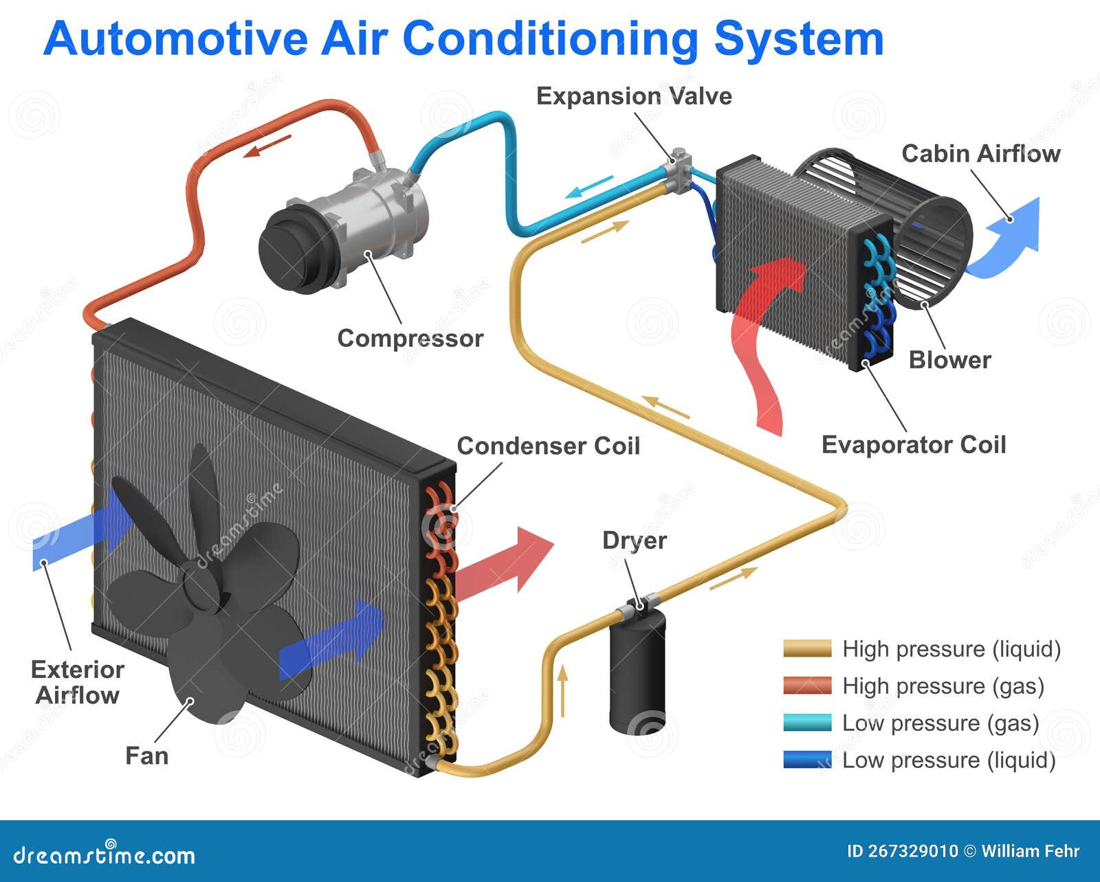
If you're an experienced DIY mechanic or a car owner looking to understand your vehicle better, diving into the workings of your auto air conditioning (A/C) system is a worthwhile endeavor. An A/C system diagram isn't just a fancy blueprint; it's your roadmap to understanding, troubleshooting, and potentially even repairing this complex but crucial system. This article will break down the diagram, its components, and how it all works together, empowering you to tackle A/C issues with confidence.
Purpose of an A/C System Diagram
Why bother with an A/C system diagram? Several reasons:
- Diagnostics: When your A/C isn't blowing cold, the diagram helps you trace the refrigerant flow and pinpoint potential problem areas.
- Repairs: Identifying components correctly is essential for ordering the right parts and performing accurate repairs.
- Understanding: Even if you don't plan on doing repairs yourself, understanding the system gives you valuable insight when discussing issues with a professional mechanic.
- Modifications: If you're considering upgrading or modifying your A/C system (e.g., adding a supplemental cooler), a diagram is crucial for planning and execution.
Key Specs and Main Parts
Before deciphering the diagram, let's review the main components of a typical automotive A/C system:
- Compressor: The heart of the system. Driven by the engine, the compressor increases the pressure and temperature of the refrigerant. Think of it like a pump that circulates the refrigerant.
- Condenser: Located in front of the radiator, the condenser dissipates heat from the high-pressure, hot refrigerant, causing it to condense into a high-pressure liquid.
- Receiver-Drier (or Accumulator): This component filters out moisture and debris from the refrigerant. It also stores excess refrigerant. The receiver-drier is typically used with a thermal expansion valve (TXV) system, while the accumulator is used with an orifice tube system.
- Expansion Valve (TXV) or Orifice Tube: This metering device controls the flow of refrigerant into the evaporator. The TXV is more responsive to changes in temperature and pressure than the simpler orifice tube.
- Evaporator: Located inside the passenger compartment, the evaporator absorbs heat from the cabin air, causing the refrigerant to evaporate into a low-pressure gas. This is where the cooling magic happens.
- Refrigerant Lines: These hoses and pipes carry the refrigerant between the components. They are designed to withstand the high pressures and temperatures within the system.
- Pressure Switches: These switches monitor the pressure in the system and can shut down the compressor if the pressure is too high or too low, protecting the components.
Symbols – Understanding the Diagram's Language
An A/C system diagram uses various symbols to represent components and lines. Here’s a breakdown of the common symbols you'll encounter:
- Lines:
- Solid Lines: Typically represent refrigerant lines.
- Dashed Lines: Often indicate control lines, such as vacuum lines or electrical wiring.
- Arrows: Indicate the direction of refrigerant flow.
- Colors: While not always consistent, some common color conventions include:
- Red: High-pressure side of the system.
- Blue: Low-pressure side of the system.
- Green: Control signals (e.g., electrical).
- Component Icons: These vary, but generally, they represent the shape and function of the component. For example:
- Compressor: Often shown as a stylized pump or circle with an "X" inside.
- Condenser/Evaporator: Usually depicted as a series of zigzag lines representing the fins.
- Receiver-Drier/Accumulator: A cylinder with desiccant inside.
- Expansion Valve: A valve symbol with a sensing bulb.
- Orifice Tube: A small restriction symbol.
It's crucial to consult the legend or key provided with the specific diagram you're using, as symbols can vary between manufacturers and models.
How It Works – The Refrigeration Cycle
The A/C system operates on a principle called the refrigeration cycle. Here's a simplified explanation:
- Compression: The compressor pumps low-pressure, low-temperature refrigerant gas, compressing it into high-pressure, high-temperature gas.
- Condensation: The high-pressure, hot gas flows to the condenser, where it releases heat to the outside air, causing it to condense into a high-pressure, warm liquid.
- Metering: The high-pressure liquid refrigerant passes through the expansion valve (TXV) or orifice tube, which restricts the flow and reduces the pressure. This pressure drop causes the refrigerant to cool significantly.
- Evaporation: The low-pressure, cold refrigerant enters the evaporator core inside the passenger compartment. As warm air from the cabin is blown across the evaporator, the refrigerant absorbs heat and evaporates into a low-pressure, cool gas. This cools the air that is blown into the cabin.
- Cycle Repeats: The low-pressure gas then returns to the compressor, and the cycle repeats.
The refrigerant acts as the heat transfer medium, moving heat from inside the car to the outside. The entire process is driven by the compressor.
Real-World Use – Basic Troubleshooting Tips
Using the A/C diagram, you can perform some basic troubleshooting. Remember that working with refrigerant requires specialized tools and knowledge, and it's often best left to professionals. However, you can do some preliminary checks:
- Visual Inspection: Check for leaks, damaged hoses, or loose connections. The diagram can help you locate specific components.
- Component Identification: The diagram ensures you're checking the correct component (e.g., confirming you're looking at the receiver-drier and not something else).
- Pressure Switch Check: Locate the pressure switches on the diagram and identify their location on the vehicle. Inspect their wiring for damage. (Note: Testing pressure switches requires specialized equipment.)
- Confirming Compressor Operation: Is the compressor clutch engaging when the A/C is turned on? Use the diagram to identify the wiring to the compressor clutch.
Example: If the diagram shows a high-pressure switch located between the condenser and the expansion valve, and your A/C isn't working, you can visually inspect the wiring and connections to that switch for damage. If they appear intact, it *might* indicate a pressure issue (but requires further diagnostics with gauges).
Safety – Handle with Care
The A/C system contains high-pressure refrigerant, which can be extremely dangerous if released improperly. Here are some critical safety precautions:
- Never disconnect A/C lines while the system is pressurized. This can result in serious injury from frostbite or refrigerant poisoning.
- Wear safety glasses and gloves when working on the A/C system.
- Refrigerant should only be handled by certified technicians with the proper equipment. Illegal venting of refrigerant is harmful to the environment and can result in fines.
- The compressor contains moving parts driven by the engine. Keep hands and clothing clear of the compressor and belt when the engine is running.
Always consult your vehicle's service manual and follow all safety precautions when working on the A/C system. If you're uncomfortable with any procedure, seek the assistance of a qualified mechanic.
Understanding your auto A/C system is a valuable skill for any car enthusiast or DIY mechanic. With the help of a detailed diagram and a basic understanding of the refrigeration cycle, you can confidently diagnose problems and potentially even perform minor repairs. Always prioritize safety and consult with a professional when necessary. We have a generic diagram file available for download. Feel free to reach out and request it!