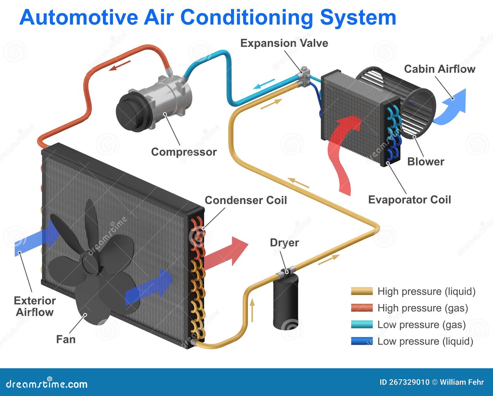
Diagram Of Automotive Air Conditioning System
Okay, let's dive into the automotive air conditioning (A/C) system. Understanding this system is crucial whether you're diagnosing a problem, planning a repair, or simply wanting to learn more about your car's inner workings. This article will break down the A/C system diagram, making it accessible to those of you who like to get your hands dirty with your vehicles.
Purpose of Understanding the A/C Diagram
Why bother learning to read an A/C diagram? It's simple: it's the blueprint for your entire system. A good diagram will allow you to:
- Diagnose problems more effectively: Trace refrigerant leaks, identify faulty components, and understand the flow of the refrigerant.
- Perform repairs with confidence: Know where each component is located, how it's connected, and what parts you'll need.
- Plan modifications or upgrades: If you're considering upgrading your compressor or adding a larger condenser, the diagram will give you the necessary layout.
- Save money: By understanding the system, you might be able to avoid unnecessary trips to the mechanic.
Key Specs and Main Parts
Before we decipher the diagram's symbols, let's cover the core components of an automotive A/C system. Remember, variations exist between vehicle makes and models, but the fundamental principles remain the same. These components are the building blocks represented on the diagram.
- Compressor: The heart of the system. Driven by the engine, the compressor pressurizes the refrigerant, increasing its temperature. This is usually a belt-driven, clutch-activated unit.
- Condenser: Located in front of the radiator, the condenser is a heat exchanger. Hot, high-pressure refrigerant from the compressor flows through the condenser, where heat is dissipated to the atmosphere, causing the refrigerant to condense into a high-pressure liquid.
- Receiver-Drier (or Accumulator): This component acts as a filter and reservoir. It removes moisture and contaminants from the refrigerant. In systems with a thermal expansion valve (TXV), it's a receiver-drier located after the condenser. In systems with an orifice tube, it's an accumulator located after the evaporator.
- Expansion Valve (TXV) or Orifice Tube: This component meters the flow of refrigerant into the evaporator, creating a pressure drop and allowing the refrigerant to expand and cool. The TXV is a more sophisticated device that regulates refrigerant flow based on evaporator temperature, while the orifice tube is a fixed-size restrictor.
- Evaporator: Located inside the dashboard, the evaporator is another heat exchanger. The cold, low-pressure refrigerant flowing through the evaporator absorbs heat from the cabin air, causing the air to cool and be blown into the vehicle.
- Refrigerant Lines (Hoses and Tubing): These lines connect all the components, allowing the refrigerant to flow throughout the system. They're designed to withstand high pressure and temperature.
- Pressure Switches: These switches monitor the refrigerant pressure and protect the system. A low-pressure switch prevents the compressor from running if the refrigerant level is too low, while a high-pressure switch shuts down the compressor if the pressure is too high.
- Blower Motor: Circulates air across the evaporator core and into the passenger cabin.
- Control System: Includes the A/C controls on the dashboard, blend doors (which regulate the mixing of hot and cold air), and sensors that feed information to the engine control unit (ECU).
Understanding the Symbols on the Diagram
A/C system diagrams employ standardized symbols to represent components and their connections. Knowing these symbols is key to deciphering the diagram.
- Lines: Lines represent refrigerant lines. Solid lines usually indicate high-pressure lines, while dashed lines often represent low-pressure lines. Some diagrams may use different colors to distinguish between high and low sides.
- Arrows: Arrows indicate the direction of refrigerant flow. Follow the arrows to trace the refrigerant's path through the system.
- Component Symbols: Each component has a unique symbol. For example, a compressor might be represented by a circle with an arrow inside, a condenser might be depicted as a series of squiggly lines, and an expansion valve could be shown as a rectangle with a restriction. Always refer to the diagram's legend to identify the specific symbols used.
- Colors: Some diagrams use color coding to further differentiate lines and components. For instance, red might represent high-pressure, high-temperature refrigerant, while blue might indicate low-pressure, low-temperature refrigerant. Again, consult the diagram's legend.
- Electrical Symbols: A/C systems also involve electrical components like pressure switches, relays, and sensors. These are represented by standard electrical symbols.
How the A/C System Works
The A/C system operates on the principle of heat transfer using a refrigerant. Let's break down the cycle:
- Compression: The compressor pressurizes the refrigerant (typically R-134a or the newer R-1234yf), increasing both its pressure and temperature.
- Condensation: The high-pressure, hot refrigerant flows into the condenser, where it releases heat to the surrounding air. As it cools, it condenses into a high-pressure liquid.
- Metering: The high-pressure liquid refrigerant then passes through the expansion valve or orifice tube, where its pressure is reduced. This creates a significant temperature drop.
- Evaporation: The cold, low-pressure refrigerant enters the evaporator. Here, it absorbs heat from the cabin air flowing across the evaporator core. As it absorbs heat, it evaporates into a low-pressure gas.
- Return to Compressor: The low-pressure, gaseous refrigerant returns to the compressor, completing the cycle.
Pressure switches play a vital role in protecting the system. The low-pressure switch prevents the compressor from running when the refrigerant is low, preventing damage. The high-pressure switch cuts off the compressor if the pressure becomes dangerously high, preventing component failure or even an explosion. The control system manages the blower fan, blend doors, and compressor operation to maintain the desired cabin temperature.
Real-World Use: Basic Troubleshooting Tips
Here are a few common A/C problems and how the diagram can help you diagnose them:
- No Cold Air: Check the compressor clutch engagement. If the clutch isn't engaging, the problem could be a faulty pressure switch, a blown fuse, a bad relay, or a problem with the compressor itself. The diagram will show you the electrical circuit for the compressor clutch and the location of the pressure switches.
- Weak Airflow: Check the blower motor and its resistor. The diagram will show you the blower motor circuit and the location of the resistor pack. Also, check for obstructions in the air ducts.
- Refrigerant Leaks: Visually inspect the refrigerant lines and components for signs of leaks (oily residue). A UV dye can be added to the system, and a UV light can then be used to pinpoint the leak location. The diagram will show you the routing of all the refrigerant lines.
- Compressor Noise: A noisy compressor could indicate internal wear or damage. Replacing the compressor is often the only solution. The diagram confirms the compressor's location and connections.
Safety Precautions
Working on an A/C system can be dangerous. Refrigerant is under high pressure, and improper handling can cause severe injury or even death. Here are some crucial safety precautions:
- Never disconnect refrigerant lines while the system is pressurized. Always have the system properly evacuated by a qualified technician using EPA-approved equipment.
- Wear safety glasses and gloves when working with refrigerant.
- Avoid contact with liquid refrigerant. It can cause frostbite.
- Dispose of used refrigerant properly. It is illegal and environmentally harmful to vent refrigerant into the atmosphere.
- Be especially careful around the compressor. It contains moving parts and is driven by the engine.
Warning: The A/C system holds pressurized refrigerant. Improper handling can cause serious injury. Always consult a qualified technician for repairs involving refrigerant.
Finally, always consult your vehicle's specific repair manual for detailed instructions and torque specifications. This article provides a general overview; your vehicle's system may have unique features or requirements.
We have the file for the A/C diagram, so now that you've read the article, download the diagram now to better understand the A/C system.