
Diagram Of Car Air Conditioning System
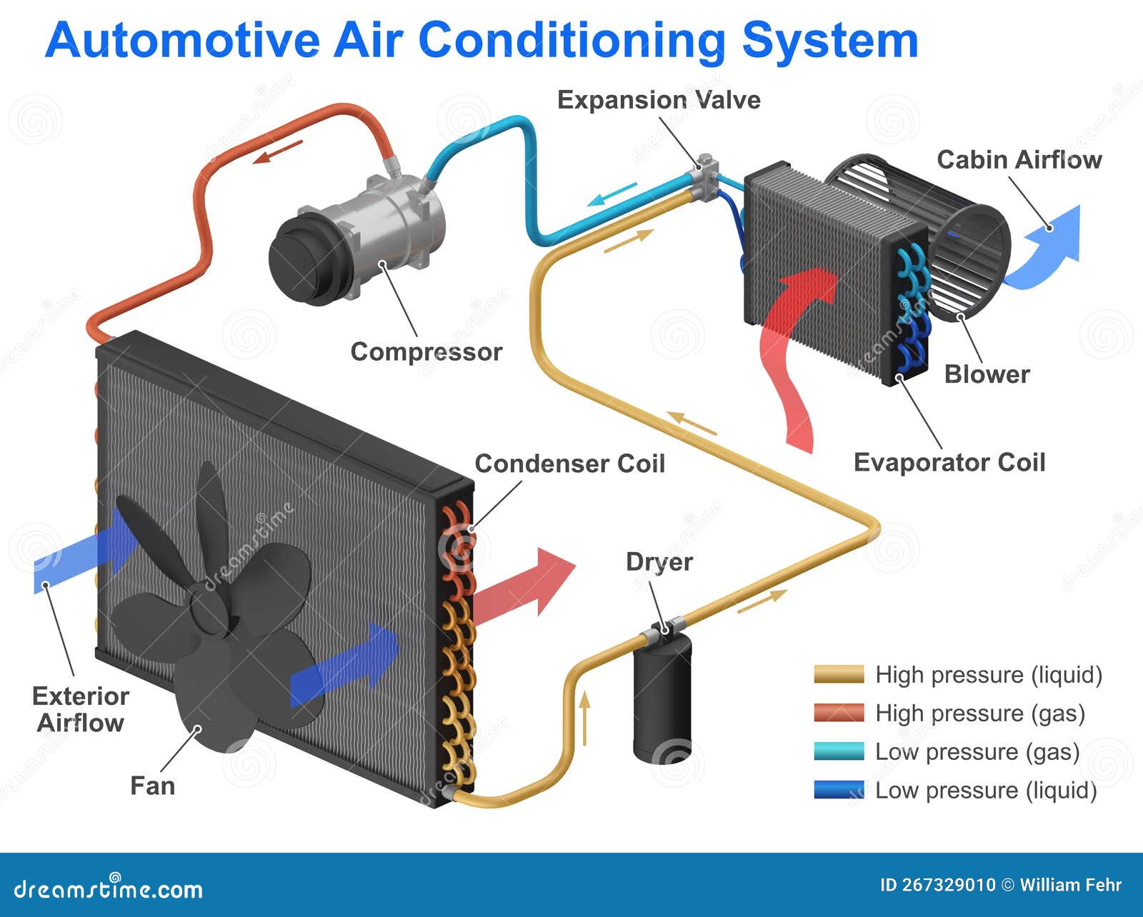
Let's delve into the heart of your car's cooling system – the air conditioning. Understanding its inner workings isn't just for professional mechanics; it empowers you to diagnose issues, perform basic maintenance, and even tackle some repairs yourself. This article provides a comprehensive breakdown of a typical car AC system diagram, equipping you with the knowledge to navigate its intricacies. We've got a detailed diagram ready for you to download too, which we will mention at the end.
Purpose of Understanding the AC Diagram
Why bother learning about this diagram? Simply put, it's your roadmap to a cooler ride. The diagram serves several critical purposes:
- Troubleshooting: When your AC starts blowing warm air, the diagram helps you pinpoint the potential culprit – a faulty compressor, a refrigerant leak, or a clogged orifice tube.
- Repair and Maintenance: Whether you're replacing a condenser or charging the system, the diagram guides you through the process, ensuring you connect the right parts in the right order.
- Performance Optimization: Understanding the system's flow allows you to identify bottlenecks and optimize performance for maximum cooling efficiency.
- Knowledge and Confidence: Simply put, knowing how things work gives you a sense of control and understanding over your vehicle.
Key Specs and Main Parts
The car AC system is a closed-loop system that relies on the principles of thermodynamics to transfer heat from inside your car to the outside. Let's break down the key components:
Main Components:
- Compressor: The heart of the system, the compressor circulates refrigerant throughout the AC loop. It increases the refrigerant's pressure and temperature. Usually driven by the engine via a belt.
- Condenser: Located in front of the radiator, the condenser dissipates heat from the high-pressure, high-temperature refrigerant, causing it to condense into a liquid.
- Receiver-Drier (or Accumulator): This component removes moisture and contaminants from the refrigerant. The receiver-drier is used in systems with a thermal expansion valve, while the accumulator is used in systems with an orifice tube.
- Expansion Valve (or Orifice Tube): This metering device controls the flow of refrigerant into the evaporator. The expansion valve is a more sophisticated and adjustable device, while the orifice tube is a simpler, fixed-size restrictor.
- Evaporator: Located inside the passenger compartment, the evaporator absorbs heat from the air blown across it, cooling the interior of the car. The refrigerant evaporates into a low-pressure gas in the process.
- Refrigerant Lines: These are the pipes that carry the refrigerant between the components.
- Refrigerant: The working fluid that carries heat throughout the system. Common refrigerants include R-134a and the newer R-1234yf.
- Blower Motor: Circulates air through the evaporator core and into the passenger compartment.
- Pressure Switches: Monitor refrigerant pressure and protect the system from damage. A low-pressure switch prevents the compressor from running when the refrigerant level is too low, while a high-pressure switch shuts down the system if the pressure gets too high.
Key Specifications to Consider:
- Refrigerant Type and Charge: Using the wrong refrigerant or an incorrect charge level can severely damage your AC system. Refer to your vehicle's service manual for the correct specifications.
- Compressor Type: Different compressor types (e.g., scroll, rotary, piston) have varying performance characteristics and maintenance requirements.
- Operating Pressures: Understanding the normal operating pressures (both high-side and low-side) is crucial for diagnosing problems.
Symbols: Deciphering the Diagram
AC system diagrams use a standardized set of symbols to represent components and their connections. Here's a breakdown of common symbols:
- Lines:
- Solid Lines: Typically represent refrigerant lines.
- Dashed Lines: Often indicate electrical wiring or vacuum lines.
- Arrows: Show the direction of refrigerant flow.
- Colors: While not always consistent, colors are often used to distinguish between high-pressure and low-pressure lines.
- Red: Usually represents high-pressure lines.
- Blue: Usually represents low-pressure lines.
- Component Icons:
- Compressor: Often depicted as a circle with a gear or piston inside.
- Condenser: Usually shown as a zigzag pattern with fins.
- Receiver-Drier: Typically represented as a cylinder with desiccant inside.
- Expansion Valve: Often depicted as a valve symbol with an arrow indicating adjustability.
- Evaporator: Usually shown as a zigzag pattern similar to the condenser, but located inside the passenger compartment.
- Pressure Switches: Represented as electrical switches with pressure sensors.
How It Works: The Cooling Cycle
The AC system operates on a closed thermodynamic cycle. Here's a simplified explanation:
- Compression: The compressor compresses the low-pressure, low-temperature refrigerant gas into a high-pressure, high-temperature gas.
- Condensation: The high-pressure, high-temperature gas flows to the condenser, where it dissipates heat and condenses into a high-pressure, high-temperature liquid.
- Metering: The high-pressure liquid refrigerant passes through the expansion valve or orifice tube, which reduces the pressure and temperature of the refrigerant. This creates a low-pressure, low-temperature liquid.
- Evaporation: The low-pressure, low-temperature liquid flows to the evaporator, where it absorbs heat from the air blowing across it, causing the refrigerant to evaporate into a low-pressure, low-temperature gas. This cools the air entering the passenger compartment.
- Return: The low-pressure gas returns to the compressor to repeat the cycle.
Real-World Use: Basic Troubleshooting
Here are a few basic troubleshooting tips using the AC diagram as your guide:
- No Cold Air: Check the compressor clutch engagement. If it's not engaging, look for electrical issues or low refrigerant pressure. Use the diagram to trace the wiring for the clutch.
- Weak Airflow: Check the blower motor and its resistor. The diagram will show the blower motor's location and wiring.
- Leaking Refrigerant: Use a UV dye and a black light to locate leaks. Common leak points include the compressor, condenser, and hose connections. The diagram will help you identify the location of these components.
- High Pressure Readings: Restricted condenser airflow. Check for debris blocking the condenser.
- Low Pressure Readings: Low refrigerant. Add refrigerant using proper charging procedures.
Safety: Handle with Care
Working on AC systems involves potentially hazardous components. Always exercise extreme caution:
- Refrigerant: Refrigerant can cause frostbite and asphyxiation. Always wear safety glasses and gloves when handling refrigerant. Never release refrigerant into the atmosphere.
- High Pressure: The system operates under high pressure. Disconnecting lines without properly evacuating the system can cause serious injury.
- Electrical Components: Be cautious when working with electrical components, especially the compressor clutch and pressure switches. Disconnect the battery before working on the electrical system.
Before attempting any repairs, consult your vehicle's service manual and follow all safety precautions. If you're not comfortable working on the AC system, seek the help of a qualified technician.
Remember the detailed diagram we mentioned? You can download it here to get a closer look at your car's AC system. This diagram, combined with the knowledge you've gained here, will be a valuable asset in your DIY automotive endeavors.