Diagram Of Crankshaft Position Sensor
Alright, let's talk about the Crankshaft Position (CKP) sensor diagram. If you're digging into engine diagnostics, tuning, or even just trying to understand how your car ticks, grasping the CKP sensor and its wiring is crucial. We’re going to break down a typical CKP sensor diagram, covering everything from its purpose to troubleshooting, making it accessible even if you're not a seasoned professional. And hey, we've got a sample diagram available for download – more on that later.
Why Bother with a CKP Sensor Diagram?
Why should you care about a CKP sensor diagram? Simple: it's your roadmap to understanding and fixing issues related to engine timing and ignition. Here's why it matters:
- Diagnostics: A CKP sensor failure can cause a no-start condition, misfires, or poor engine performance. The diagram helps you pinpoint whether the sensor itself, its wiring, or the Engine Control Unit (ECU) is the problem.
- Repairs: If you're replacing the CKP sensor or repairing damaged wiring, the diagram ensures you connect everything correctly.
- Tuning and Modifications: When modifying your engine, understanding the CKP signal is crucial for proper ECU calibration and performance tuning. It's fundamental to understanding ignition timing.
- Learning: Even if you're just curious, the diagram visually explains how the CKP sensor interacts with the rest of the engine management system.
Key Specs and Main Parts
A typical CKP sensor system consists of these main components:
- Crankshaft Position Sensor (The CKP Sensor): The heart of the system, it detects the position (and sometimes speed) of the crankshaft. Two common types exist:
- Magnetic Inductive Sensors (Variable Reluctance): These sensors generate an AC voltage signal. They typically have two wires.
- Hall Effect Sensors: These sensors require a power supply and output a digital (square wave) signal. They usually have three wires: power, ground, and signal.
- Tone Ring (Reluctor Wheel): A toothed wheel or notched disc attached to the crankshaft. As the crankshaft rotates, the teeth or notches pass by the CKP sensor. The frequency of these passing teeth or notches directly correlates to engine speed (RPM).
- Wiring Harness: Connects the CKP sensor to the ECU. Look for corrosion, breaks, or shorts in the wiring.
- Engine Control Unit (ECU): Processes the CKP sensor signal to determine engine speed, crankshaft position, and ignition timing. This is where the magic (and the complexity) happens.
Understanding the Diagram: Symbols, Lines, and Colors
Let's decode a typical CKP sensor wiring diagram. These are some of the common elements you'll encounter:
- Lines: Lines represent wires. Their thickness can sometimes, but not always, indicate wire gauge. A solid line means a direct connection. A dashed line might indicate a shielded wire or a connection through a connector.
- Colors: Wire colors are usually indicated by abbreviations (e.g., "BLK" for black, "RED" for red, "GRN" for green, "BLU" for blue, "YEL" for yellow, "WHT" for white). These colors are critical for tracing wires in the engine bay.
- Connectors: Shown as circles, squares, or specialized symbols. They indicate where wires connect and disconnect. The diagram will ideally show the connector pin numbers, making it easier to identify the correct wire.
- Ground Symbols: Look for the ground symbol, which resembles an inverted triangle with horizontal lines. This indicates the ground point for the sensor or ECU.
- ECU Pin Numbers: The diagram should clearly label which ECU pin the CKP sensor wires connect to.
- Sensor Symbols: The CKP sensor itself is typically represented by a rectangle or square with connecting wires. The diagram might also indicate the sensor type (e.g., "Hall Effect CKP Sensor").
- Voltage Symbols: You might see "12V" or "5V" near power wires. This indicates the voltage supplied to the sensor.
How It Works: From Tone Ring to Timing
The CKP sensor's operation is relatively straightforward, but its impact is significant:
- Rotation: The crankshaft rotates, and with it, the tone ring.
- Signal Generation: As the teeth (or notches) of the tone ring pass the CKP sensor, the sensor generates a signal.
- Magnetic Inductive (Variable Reluctance): The passing teeth alter the magnetic field, inducing an AC voltage in the sensor coil. The frequency and amplitude of the AC voltage change with engine speed.
- Hall Effect: The passing teeth interrupt a magnetic field within the sensor. This causes the Hall Effect sensor to switch its output signal on and off, creating a square wave (digital signal).
- Signal Transmission: The signal is sent to the ECU via the wiring harness.
- ECU Processing: The ECU interprets the signal to determine:
- Engine Speed (RPM): Based on the frequency of the signal.
- Crankshaft Position: By referencing the position of a specific tooth or notch on the tone ring. Usually there's a missing tooth or a special mark on the ring that the ECU uses as a synchronization point.
- Ignition and Fuel Injection Timing: Using this information, the ECU precisely controls ignition timing and fuel injection to optimize engine performance.
Real-World Use: Basic Troubleshooting
Here's how you can use the diagram for basic troubleshooting:
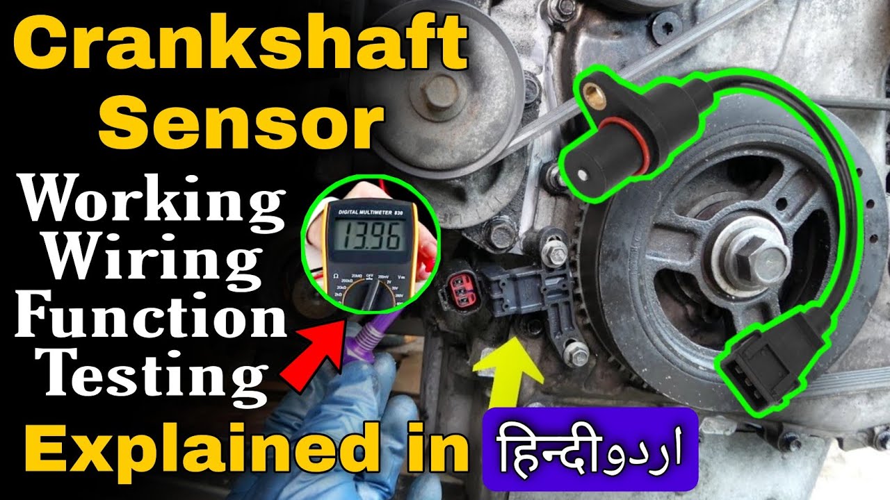
- No-Start Condition: If your car won't start, check the CKP sensor signal with a multimeter or oscilloscope. The diagram will show you which pins to test and what voltage or waveform to expect.
- Misfires: Intermittent misfires can be caused by a faulty CKP sensor or wiring. Use the diagram to inspect the wiring harness for damage or loose connections.
- Code Reading: Use an OBD-II scanner to read diagnostic trouble codes (DTCs). Codes like P0335 (Crankshaft Position Sensor A Circuit) or P0336 (Crankshaft Position Sensor A Circuit Range/Performance) indicate a problem with the CKP sensor or its circuit.
- Continuity Testing: Use a multimeter to check the continuity of the wires between the CKP sensor and the ECU. The diagram will show you the correct wire colors and pin locations.
- Signal Testing: Use an oscilloscope to visually inspect the CKP sensor signal. A healthy signal should be a clean sine wave (for magnetic inductive sensors) or a square wave (for Hall Effect sensors). Distorted or missing signals indicate a problem.
Safety First!
Working with electrical components always carries risks. Here are some crucial safety tips:
- Disconnect the Battery: Always disconnect the negative battery terminal before working on any electrical components.
- Avoid Shorts: Be careful not to short circuit any wires. This can damage the ECU or other electrical components.
- Use Proper Tools: Use insulated tools to prevent electrical shock.
- Don't Probe Connectors with Sharp Objects: Use back-probing techniques or specialized connector testing tools to avoid damaging the connector pins.
- Be Mindful of Hot Components: The engine can get extremely hot! Ensure the engine has cooled down before touching any components.
- High Voltage Components: Ignition coils and capacitors associated with ignition systems can store dangerous high voltages. Ensure that the ignition system is fully discharged before handling these components. This usually involves waiting a period of time after the engine has been shut off.
Remember that this information is for general guidance only. Always refer to the specific repair manual for your vehicle for detailed instructions and diagrams.
So, there you have it – a breakdown of the CKP sensor diagram. By understanding the purpose, components, and troubleshooting techniques, you'll be better equipped to diagnose and repair engine-related issues.
As promised, we have a sample CKP sensor diagram ready for you to download. It's a great visual aid to reinforce what we've covered here.