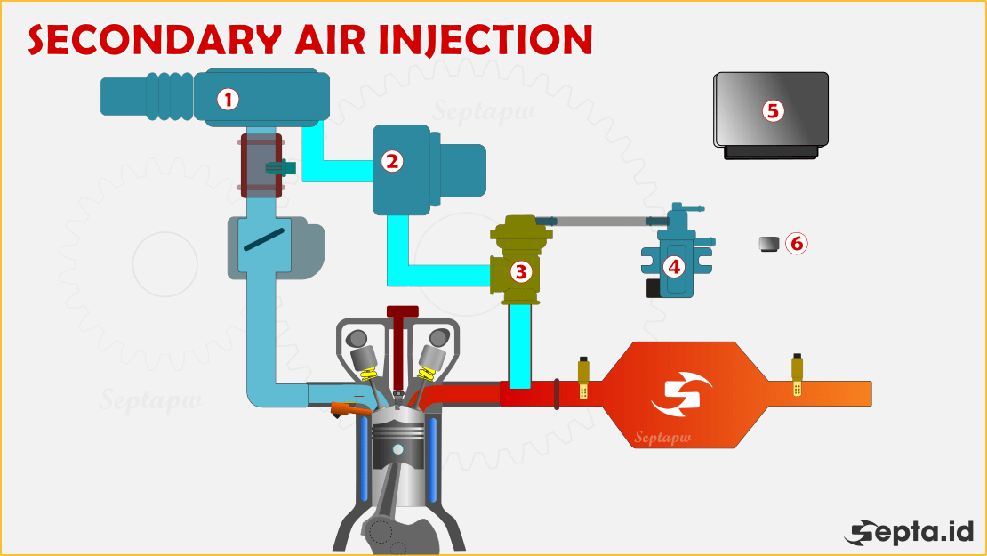
Diagram Secondary Air Injection System
Understanding your vehicle's Secondary Air Injection (SAI) system is crucial for maintaining optimal emissions performance, especially if you're tackling repairs, modifications, or simply want a deeper understanding of your engine's operation. This article will delve into the intricacies of the SAI system, using a diagram as our guide to navigate its components and functionality.
Purpose – Why This Diagram Matters
A detailed diagram of the SAI system is invaluable for several reasons:
- Diagnostics: When your vehicle throws an emissions-related code, particularly those concerning lean conditions or catalytic converter efficiency, the SAI system is often a suspect. A diagram allows you to trace the system's components and identify potential faults.
- Repairs: Replacing faulty valves, pumps, or hoses requires a clear understanding of their location and connection points. The diagram provides a visual roadmap for disassembly and reassembly.
- Modifications: Some enthusiasts choose to delete or modify their SAI systems for performance reasons (although this may violate emissions regulations). A diagram is essential for planning and executing these modifications correctly.
- Learning: Simply understanding how your engine operates can be a rewarding experience. The SAI system, while relatively simple, plays a vital role in reducing harmful emissions.
By understanding the SAI system diagram, you empower yourself to diagnose, repair, and even modify your vehicle with confidence.
Key Specs and Main Parts
The specific components of the SAI system vary depending on the make, model, and year of your vehicle, but the core elements remain consistent. Here's a breakdown of the key parts:
- Secondary Air Injection Pump: The heart of the system. This electric (most common) or belt-driven (less common) pump forces fresh air into the exhaust stream. Key specs include voltage (typically 12V), flow rate (measured in cubic feet per minute - CFM), and operating temperature range.
- Check Valve(s) (One-Way Valve(s)): Prevents exhaust gases from flowing back into the air pump when it's not operating. These valves are critical; a failed check valve can lead to pump damage. Some vehicles have multiple check valves.
- Air Distribution Manifold/Rail: Distributes the air from the pump to the exhaust ports of the engine, usually located on the cylinder head.
- Air Injection Nozzles: Located on the cylinder head near the exhaust ports, inject fresh air directly into the exhaust stream.
- SAI Relay: An electrical relay that controls the power to the SAI pump, typically controlled by the Engine Control Unit (ECU).
- Vacuum Lines (if applicable): Some systems utilize vacuum to control valves or dampers that regulate airflow.
- Hoses and Connectors: Connect all the components. These are susceptible to cracking and leaks due to heat and age.
- ECU (Engine Control Unit): The brain of the system, controlling the pump's operation based on engine temperature, load, and other parameters. The ECU monitors the Oxygen sensors to determine catalytic converter effectiveness.
Symbols – Explaining Lines, Colors, and Icons
Understanding the symbols used in the SAI diagram is crucial for interpreting its information correctly. Common symbols include:
- Solid Lines: Typically represent hard lines or hoses carrying air under pressure. The thickness of the line *may* indicate the diameter of the hose.
- Dashed Lines: Often indicate vacuum lines or control signals.
- Dotted Lines: Can represent electrical wiring or sensor connections.
- Arrows: Indicate the direction of airflow or electrical current.
- Rectangles: Usually represent electrical components like relays or sensors.
- Circles: May represent valves or connections.
- Color Coding: Some diagrams use color coding to differentiate between different types of lines or fluids. For example, blue might represent air, while green could represent vacuum. Refer to the diagram's legend for clarification.
Pay close attention to the legend provided with the diagram, as symbol conventions can vary. Different OEMs may use different symbols. If the legend is unclear, research the specific vehicle's service manual for further clarification.
How It Works
The SAI system operates during the engine's cold start phase. Here's a simplified explanation of the process:
- When the engine is cold, the ECU detects this condition via the Engine Coolant Temperature (ECT) sensor.
- The ECU activates the SAI relay, which in turn powers the SAI pump.
- The pump draws in fresh air (usually filtered from the engine's air intake) and forces it through the air distribution manifold/rail.
- The air is then injected into the exhaust stream near the exhaust ports on the cylinder head.
- The injected air helps to burn any unburnt hydrocarbons (fuel) in the exhaust, reducing harmful emissions and quickly heating up the catalytic converter to its optimal operating temperature. A warm catalytic converter is able to scrub pollutants from the exhaust more effectively.
- Once the engine reaches its normal operating temperature (usually within a few minutes), the ECU deactivates the SAI pump, and the system shuts down until the next cold start.
The check valve(s) prevent exhaust gases from backflowing into the pump when it's not running, protecting it from damage and corrosion. The entire process is monitored by the ECU, which uses oxygen sensor readings to verify the system's effectiveness. If the ECU detects a problem, it will trigger a diagnostic trouble code (DTC) and illuminate the check engine light (CEL).
Real-World Use – Basic Troubleshooting Tips
Here are some basic troubleshooting tips for the SAI system, based on symptoms and common failure points:
- Check Engine Light (CEL) with SAI Codes (e.g., P0410, P0411): Inspect the pump for proper operation. Listen for the pump running during a cold start. Check the SAI relay and associated wiring. A multimeter can be used to test the relay and pump for continuity and voltage.
- Pump Not Running: Check the fuse for the SAI system. Test the SAI relay. Inspect the wiring harness for damage or corrosion. If the pump is receiving power but not running, it's likely faulty.
- Loud Noise from Pump: The pump may be failing or have debris inside. Remove and inspect the pump. Replacement is usually the best option.
- Exhaust Gases Leaking from SAI System: This is a strong indication of a faulty check valve. Replace the check valve(s) immediately to prevent pump damage. Inspect the hoses for cracks and leaks.
- Lean Codes (e.g., P0171, P0174): While less common, a malfunctioning SAI system *can* contribute to lean codes if it's injecting excessive air into the exhaust, skewing the oxygen sensor readings. Thoroughly test other potential causes of lean codes before focusing on the SAI system.
Important Note: Always refer to your vehicle's specific service manual for detailed troubleshooting procedures and diagnostic information. Generic OBD-II codes can provide a starting point, but manufacturer-specific codes offer more precise guidance.
Safety – Highlight Risky Components
Working on the SAI system involves some potential safety hazards:
- Electrical Hazards: The SAI pump is powered by high voltage (typically 12V). Disconnect the battery before working on any electrical components to prevent shocks or shorts.
- Hot Exhaust Components: Avoid touching the exhaust manifold or catalytic converter, especially after the engine has been running. These components can reach extremely high temperatures and cause severe burns.
- Moving Parts: Be cautious of moving parts, such as the engine cooling fan and serpentine belt, when working near the engine bay. Ensure the engine is off and the key is removed before performing any repairs.
- Air Pump: When disconnecting air lines, ensure the system is not currently running. Disconnecting the lines from the pump while it is operating can result in blowing debris into your face and eyes.
Always wear appropriate personal protective equipment (PPE), such as safety glasses and gloves, when working on your vehicle.
By understanding the diagram and following safe practices, you can effectively diagnose and repair your vehicle's Secondary Air Injection system, ensuring optimal emissions performance and preventing costly repairs.
We have a sample SAI diagram file available for download that illustrates the principles discussed in this article. This example is a generalized representation and may not perfectly match your vehicle's specific configuration, but it will provide a helpful visual reference.