Diagram Steering Wheel Control Key 1 Key 2 Wires
Understanding your steering wheel control (SWC) wiring is crucial for various automotive tasks, ranging from simple audio upgrades to more complex modifications like integrating aftermarket electronic components. This guide will break down a typical SWC wiring diagram, focusing on Key 1, Key 2, and ground wires. We'll cover their purpose, how they work, troubleshooting common issues, and most importantly, safety precautions.
Why Understanding SWC Wiring Matters
Whether you're replacing a faulty head unit, adding a new interface to control aftermarket devices, or simply learning more about your vehicle's electrical system, knowing how the SWC wiring functions is essential. A clear understanding allows for:
- Precise Installations: Connecting aftermarket components correctly without damaging the vehicle's electrical system.
- Efficient Troubleshooting: Diagnosing and resolving SWC malfunctions quickly.
- Preventing Electrical Damage: Avoiding short circuits and other electrical issues that can arise from improper wiring.
Key Specs and Main Parts
A typical SWC system consists of the following key components:
- Steering Wheel Control Module (if equipped): This module interprets the resistance values from the buttons and sends a signal to the head unit or vehicle's CAN bus. Some vehicles have this integrated into the Body Control Module (BCM).
- Steering Wheel Control Buttons: These are the physical buttons on your steering wheel that control functions like volume, track selection, answering calls, and more.
- Wiring Harness: The bundle of wires connecting the buttons to the head unit or control module. This is where we find the Key 1, Key 2, and ground wires.
- Head Unit/Radio: The receiver in your dashboard that receives the SWC signals and performs the requested actions.
- Resistors: Each button on the steering wheel corresponds to a different resistance value. These resistors are often built into the button assembly.
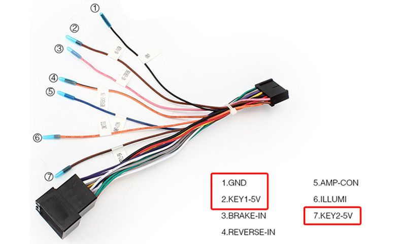
The main wires of interest in most SWC systems are:
- Key 1 (Signal 1): This wire carries a variable resistance signal from the SWC buttons to the head unit. Each button press changes the resistance, which the head unit interprets as a specific command.
- Key 2 (Signal 2): Some systems use a second signal wire to provide additional control options or to improve signal accuracy. Key 2 functions in a similar manner to Key 1, providing a different set of resistance values for different commands. Often, if Key 2 isn't present, Key 1 handles all functions.
- Ground: Provides the return path for the electrical circuit. A good ground connection is essential for proper SWC operation. Often this will be a chassis ground, meaning it connects directly to the metal frame of the vehicle.
Symbols – Deciphering the Diagram
SWC wiring diagrams use standardized symbols to represent electrical components and connections. Here's a breakdown of common symbols:
- Solid Line: Represents a wire. Thicker lines may indicate wires carrying higher current.
- Dashed Line: Can represent a shielded wire or a connection hidden behind a panel.
- Colors: Each wire is typically identified by a specific color (e.g., red for power, black for ground, yellow/blue for Key 1, green/white for Key 2). Consult your vehicle's specific wiring diagram for the color codes.
- Ground Symbol: A series of horizontal lines decreasing in size, indicating a connection to ground.
This symbol is often stylized, but the basic shape remains consistent.
- Resistor Symbol: A zig-zag line. The value of the resistor (in ohms) may be indicated next to the symbol.
- Connector Symbol: A rectangle or a circle, often with numbers or letters to identify the pin connections.
Understanding these symbols is critical for accurately interpreting the wiring diagram and making correct connections.
How It Works: Resistance is Key
The core principle behind SWC systems is variable resistance. When you press a button on the steering wheel, you're essentially changing the resistance in the circuit. The head unit (or SWC module) reads this resistance and translates it into a specific command.
- Button Press: Pressing a button on the steering wheel closes a circuit containing a specific resistor.
- Resistance Change: This action changes the overall resistance of the circuit on the Key 1 (or Key 2) wire.
- Signal Transmission: The change in resistance creates a specific voltage level on the Key 1/Key 2 wire. This voltage signal is sent to the head unit or SWC module.
- Command Interpretation: The head unit or SWC module is programmed to recognize specific voltage levels as specific commands (e.g., increasing volume, changing tracks).
- Action Execution: The head unit or module then executes the corresponding command.
The Key 2 wire, when present, functions similarly. It allows for more granular control or the implementation of more functions without overloading the Key 1 wire with too many resistance values. A CAN bus system is much different and works via digital signaling.
Real-World Use: Troubleshooting Tips
Here are some common SWC issues and basic troubleshooting tips:
- No SWC Functionality:
- Check the Fuse: Make sure the fuse for the radio or SWC system is not blown.
- Inspect Wiring: Look for loose connections, damaged wires, or corrosion in the wiring harness, especially around connectors.
- Verify Ground Connection: Ensure the ground wire is securely connected to a clean, unpainted metal surface on the vehicle's chassis. A bad ground can cause intermittent or complete failure.
- Test Key 1/Key 2 Voltage: Use a multimeter to check the voltage on the Key 1 and Key 2 wires when buttons are pressed. You should see a change in voltage corresponding to each button. If there's no change, the problem could be with the buttons themselves or the wiring leading to them.
- Head Unit Compatibility: If you've installed an aftermarket head unit, ensure it's compatible with your vehicle's SWC system and that the SWC adapter is properly installed and programmed.
- Incorrect Button Functionality:
- Programming Issues: If you've installed a new head unit or SWC adapter, ensure it's properly programmed to recognize the button commands.
- Resistance Issues: The resistance values for the buttons may be incorrect due to damaged resistors or wiring issues.
- Intermittent Functionality:
- Loose Connections: Check for loose or corroded connections in the wiring harness.
- Temperature Sensitivity: Some components can be temperature-sensitive, causing intermittent issues in extreme heat or cold.
Safety First: Handle with Care
Working with automotive electrical systems can be dangerous. Always follow these safety precautions:
- Disconnect the Battery: Before working on any electrical system, disconnect the negative terminal of the battery to prevent short circuits and potential shocks. This is non-negotiable.
- Use Proper Tools: Use insulated tools designed for automotive electrical work.
- Avoid Cutting Wires Unnecessarily: Identify the correct wires before cutting or splicing. Use a wiring diagram to confirm the wire's function and color code.
- Be Careful with Airbags: Some steering wheels contain airbags. Disconnect the airbag system before removing the steering wheel to avoid accidental deployment. Consult a professional if you are not comfortable working with airbags. Airbag deployment can cause serious injury.
- Double-Check Connections: Before reconnecting the battery, double-check all wiring connections to ensure they are secure and properly insulated.
Always prioritize safety when working with your vehicle's electrical system. If you're unsure about any aspect of the process, consult a qualified automotive electrician.
Understanding your vehicle's SWC wiring can empower you to tackle various automotive projects with confidence. By learning the purpose of each wire, how the system works, and troubleshooting common issues, you can save time and money while gaining valuable knowledge about your car's electrical system.
We have the SWC diagram as a separate downloadable file that you can use for your reference.