
Diagram Suspension Parts Names With Pictures
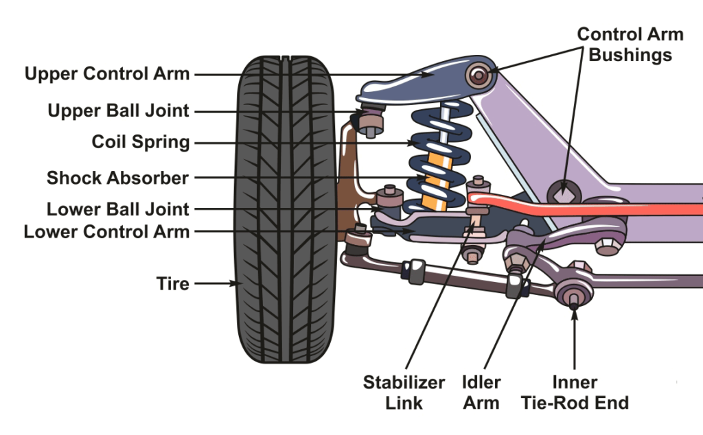
Understanding your car's suspension system is crucial for performing repairs, diagnosing problems, and even making informed decisions about modifications. A detailed suspension diagram is your roadmap to navigating this complex system. This guide will walk you through a typical suspension diagram, explaining the components, their functions, and how to interpret the information presented.
Why You Need a Suspension Diagram
Suspension diagrams are indispensable for several reasons:
- Repairs: Identifying the exact part needing replacement is paramount. A diagram shows its location and relationship to other components.
- Diagnosis: Tracing the source of a suspension issue, such as a clunking noise or uneven tire wear, becomes easier with a visual guide.
- Modifications: Planning upgrades, like installing lowering springs or performance shocks, requires knowing the suspension layout and compatibility of aftermarket parts.
- Learning: Even if you're not actively working on your car, understanding the suspension system improves your overall automotive knowledge.
Key Suspension Parts and Their Functions
Let's break down the major components you'll find in a typical suspension diagram. Keep in mind that specific designs vary between vehicle makes and models (e.g., MacPherson strut, double wishbone, leaf spring), but the core principles remain the same.
Front Suspension

(Example Diagram - Consult Your Vehicle's Specific Diagram for Accurate Representation)
- Strut/Shock Absorber: This dampens oscillations and controls suspension movement. It's typically a hydraulic or gas-filled cylinder that converts kinetic energy into heat.
- Coil Spring: Provides the springing action to absorb bumps and maintain ride height. Its spring rate determines how stiff the suspension is.
- Control Arms (Upper & Lower): These connect the wheel hub to the vehicle's frame or subframe. They allow the wheel to move up and down while maintaining proper alignment. Also known as A-arms.
- Ball Joints: Spherical bearings that allow the control arms to pivot and the steering knuckle to turn. Critical for steering responsiveness and safety.
- Steering Knuckle/Spindle: Connects the wheel hub to the control arms and steering linkage. Houses the wheel bearing and provides a mounting point for the brake caliper.
- Tie Rods (Inner & Outer): Part of the steering linkage. They transmit steering force from the steering rack to the steering knuckles, causing the wheels to turn.
- Sway Bar/Anti-Roll Bar: Connects the left and right sides of the suspension. It resists body roll during cornering by transferring force between the wheels. Its torsional stiffness influences handling characteristics.
- Sway Bar Links/End Links: Connect the sway bar to the control arms or struts.
Rear Suspension
(Example Diagram - Consult Your Vehicle's Specific Diagram for Accurate Representation)
- Strut/Shock Absorber: Same function as in the front suspension – dampens oscillations.
- Coil Spring (or Leaf Spring): Provides springing action. Leaf springs are commonly found in trucks and older vehicles.
- Control Arms (Trailing Arms, Lateral Links): Similar to the front, these connect the wheel hub to the frame. Different designs exist, each with its own characteristics.
- Axle (in live axle setups): A solid beam connecting the rear wheels. Found in older vehicles and some trucks.
- Sway Bar/Anti-Roll Bar: Resists body roll.
- Sway Bar Links/End Links: Connect the sway bar to the control arms or struts.
- Panhard Rod (in some live axle setups): A lateral bar that locates the axle and prevents side-to-side movement.
Understanding Diagram Symbols
Suspension diagrams aren't just pictures; they use standardized symbols and conventions:
- Lines: Solid lines generally represent physical components. Dashed lines might indicate hidden parts or connections.
- Arrows: Indicate direction of movement or force. For example, an arrow pointing along a spring indicates the direction of its compression.
- Shading/Color: Some diagrams use color-coding to differentiate between different materials or systems. Consult the diagram's legend for the specific meaning.
- Icons: Simplified representations of components, like a coil symbol for a coil spring or a rectangle for a bushing.
- Numerical Callouts: Numbers or letters pointing to specific parts, cross-referenced to a parts list or exploded view.
How the Suspension System Works
The suspension system's primary job is to isolate the vehicle body from road imperfections, providing a comfortable ride and maintaining tire contact with the road for optimal handling and braking.
When a wheel encounters a bump, the spring compresses, absorbing the initial impact. The shock absorber then dampens the spring's oscillations, preventing the vehicle from bouncing excessively. Control arms guide the wheel's movement, ensuring it travels in the correct arc. The sway bar minimizes body roll during cornering, improving stability.
Real-World Use: Basic Troubleshooting
A suspension diagram can be a valuable tool for diagnosing common issues:
- Clunking Noises: Check bushings (especially sway bar bushings and control arm bushings) for wear and play. Look for broken sway bar links.
- Squeaking Noises: Could indicate dry ball joints or worn bushings.
- Uneven Tire Wear: May be caused by misaligned suspension components. Check ball joints, tie rod ends, and control arm bushings. A suspension diagram can help you identify these components and their locations.
- Excessive Bouncing: Indicates worn shock absorbers.
- Wandering Steering: Can be caused by loose ball joints, tie rod ends, or worn steering rack bushings.
Always confirm the component location using your specific diagram.
Safety Considerations
Working on the suspension system can be dangerous. Springs are under immense pressure and can cause serious injury if released suddenly. Always use proper spring compressors when working with coil springs or leaf springs.
Before disconnecting any suspension component, ensure the vehicle is properly supported on jack stands. Never work under a vehicle supported only by a jack.
Brake lines are often routed through or near suspension components. Exercise extreme caution when working near them to avoid damage or leaks. Brake fluid is corrosive and can damage paint.
Downloadable Suspension Diagram
While we've provided general information and example diagrams, the most valuable resource is a diagram specific to your vehicle. We have a generic suspension diagram file available for download (PDF format) that includes common notations and component labels. [Download Link Here] (Note: this is a generic diagram; always consult your vehicle's service manual for accurate information).
Remember to consult your vehicle's service manual for detailed instructions and torque specifications before performing any suspension work. Good luck, and be safe!