
Diagram Toyota Rear Drum Brake Assembly
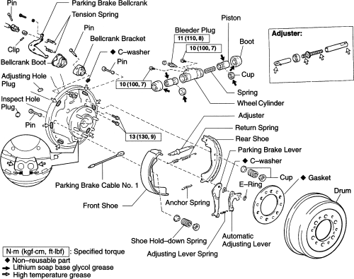
Rear drum brakes, while less common in modern front-wheel-drive vehicles, are still found on many cars, trucks, and SUVs, particularly those with rear-wheel drive or four-wheel drive. Understanding their assembly is crucial for effective maintenance, troubleshooting, and repair. This guide provides a detailed breakdown of a typical Toyota rear drum brake assembly, focusing on component identification, function, and practical application.
Purpose of the Diagram and This Guide
A diagram of the rear drum brake assembly is invaluable for several reasons. Firstly, it serves as a reference point during repairs and maintenance. Knowing the exact location and orientation of each component ensures correct reassembly. Secondly, it's an excellent learning tool. By studying the diagram, you can understand how the different parts interact to create the braking force. Finally, it aids in troubleshooting. When you're experiencing brake problems, the diagram helps you visualize the system and pinpoint potential sources of the issue. This guide complements that diagram, explaining the function and significance of each component.
Key Specifications and Main Parts
Before diving into the details, let's outline some key specifications and the main parts of a typical Toyota rear drum brake assembly. Note that variations exist between models and years, but the fundamental principles remain the same.
- Drum Diameter: The internal diameter of the brake drum, usually measured in millimeters or inches. This is a critical dimension for selecting correct brake shoes.
- Shoe Width: The width of the brake shoe friction material.
- Lining Material: The type of friction material used on the brake shoes (e.g., organic, semi-metallic).
The main components are:
- Brake Drum: The rotating component that the brake shoes press against to create friction and slow the vehicle.
- Brake Shoes: Curved metal pieces with friction material (linings) attached. These are forced against the inside of the brake drum.
- Wheel Cylinder: A hydraulic cylinder that uses brake fluid pressure to push the brake shoes outward.
- Return Springs: Springs that pull the brake shoes back away from the drum when the brake pedal is released.
- Adjuster Mechanism: A device that automatically or manually adjusts the shoe-to-drum clearance as the brake linings wear. This often includes a star wheel adjuster.
- Hold-Down Springs: Small springs and pins that hold the brake shoes against the backing plate.
- Parking Brake Lever: A lever attached to one of the brake shoes that is actuated by the parking brake cable.
- Parking Brake Strut: A small bar that transfers the parking brake force from one shoe to the other.
- Backing Plate: A stationary plate that supports all the other brake components.
Diagram Symbols: Lines, Colors, and Icons
Understanding the symbols used in the diagram is vital for interpreting it correctly. Common symbols include:
- Solid Lines: Usually represent solid components like brake shoes, drums, and the backing plate.
- Dashed Lines: Often indicate hidden components or the path of movement (e.g., brake shoe travel).
- Thin Lines: May represent springs, levers, or other smaller parts.
- Colors: Colors can sometimes be used to differentiate between components, but color-coding is not universally consistent across all diagrams. Refer to the diagram's key if colors are used.
- Icons: Icons may represent fasteners (bolts, nuts, clips), fluid connections (brake lines), or adjustment points. Again, refer to the diagram's legend.
Specific to brake systems, you'll often see hydraulic lines depicted with a distinctive symbol, indicating the presence of brake fluid under pressure.
How It Works: The Drum Brake System
The drum brake system operates on a relatively simple principle. When the brake pedal is pressed, the master cylinder sends hydraulic pressure through the brake lines to the wheel cylinder located in the rear drum brake assembly. The wheel cylinder contains pistons that are pushed outward by this pressure. These pistons then force the brake shoes against the inside surface of the rotating brake drum. The friction between the brake shoes and the drum slows the drum's rotation, which in turn slows the wheel and the vehicle.
When the brake pedal is released, the pressure in the brake lines drops, and the return springs pull the brake shoes back away from the drum. This allows the wheel to rotate freely again. The adjuster mechanism plays a crucial role in maintaining proper shoe-to-drum clearance. As the brake linings wear down, the adjuster mechanism automatically (or manually in some older systems) expands to compensate for the wear, ensuring that the brake shoes remain close enough to the drum to provide effective braking.
The parking brake operates independently of the hydraulic system. When the parking brake lever is engaged, a cable pulls on the parking brake lever within the drum brake assembly. This lever pivots and pushes the parking brake strut against the other brake shoe, forcing both shoes against the drum and locking the wheels.
Real-World Use: Basic Troubleshooting Tips
A basic understanding of the rear drum brake assembly allows for simple troubleshooting. Here are some common problems and potential causes:
- Spongy Brake Pedal: Could indicate air in the brake lines, a leaking wheel cylinder, or worn brake shoes that require excessive pedal travel.
- Brake Noise (Squealing or Grinding): Often caused by worn brake shoes, a glazed drum surface, or foreign objects trapped between the shoes and the drum.
- Parking Brake Failure: May be due to a stretched or broken parking brake cable, a seized parking brake lever within the drum brake assembly, or worn brake shoes.
- Uneven Braking: Could indicate a problem with the adjuster mechanism on one side, causing uneven shoe-to-drum clearance. Also, a leaking wheel cylinder on one side will cause reduced braking on that wheel.
- Dragging Brakes: Could be caused by sticking wheel cylinder pistons, weak return springs, or an over-adjusted brake shoe.
When troubleshooting, always inspect the brake drum for signs of wear, damage, or contamination. Check the brake shoes for wear and tear, and examine the wheel cylinder for leaks. Ensure that all springs are in good condition and properly installed. If you suspect a problem with the hydraulic system, bleed the brakes to remove any air.
Safety Considerations
Working on brake systems involves inherent risks. Brake fluid is corrosive and can damage paint and other surfaces. Always wear eye protection and gloves when handling brake fluid. Avoid getting brake fluid on your skin. Some older brake shoes may contain asbestos, which is a known carcinogen. If you are working on older vehicles, take precautions to avoid inhaling brake dust. Wet down the brake components before disassembly to minimize dust generation. Dispose of old brake shoes properly according to local regulations.
The brake springs are under tension and can cause injury if they slip during removal or installation. Use proper brake spring tools to safely remove and install these springs. Failure to reassemble the brake components correctly can result in brake failure, leading to serious injury or death. If you are not comfortable working on brake systems, it is best to seek the assistance of a qualified mechanic.
Finally, ensure that the vehicle is properly supported on jack stands before working under it. Never rely solely on a jack to support the vehicle. Before driving, test the brakes thoroughly at low speeds to ensure they are functioning correctly. Verify that the parking brake holds the vehicle securely.
We have a detailed diagram of a typical Toyota rear drum brake assembly available for download. This diagram provides a visual reference to complement the information presented in this guide, making the understanding and servicing of your vehicle's braking system easier and safer. With the diagram and this comprehensive guide, you'll be well-equipped to tackle common drum brake maintenance and repair tasks with confidence.