
Diagram What Wires Go To Ignition Switch
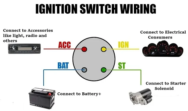
Understanding your car's ignition system is crucial for everything from basic repairs to advanced modifications. At the heart of this system lies the ignition switch, a seemingly simple component that controls the flow of power to various circuits, allowing your engine to start and run. Having a detailed diagram of what wires connect to your ignition switch is invaluable. This article provides a comprehensive breakdown of ignition switch wiring, equipping you with the knowledge to confidently diagnose issues, perform repairs, or even customize your vehicle's electrical system.
Purpose of an Ignition Switch Wiring Diagram
Why bother understanding the ignition switch wiring? Here's why a diagram is essential:
- Troubleshooting Starting Problems: Many starting problems originate with the ignition switch. A diagram allows you to identify which wires to test for voltage, ground, and continuity, pinpointing faulty connections or a failing switch.
- Wiring Repairs: Over time, wires can become brittle, corroded, or damaged. A diagram helps you correctly identify and replace damaged wiring, ensuring a reliable connection to the ignition switch.
- Security System Installation: Adding aftermarket security systems often requires tapping into the ignition switch wiring. A diagram shows you the correct wires to connect to, preventing accidental damage or malfunctions.
- Customization and Modification: If you're modifying your car's electrical system – perhaps adding a remote start or push-button ignition – a diagram helps you understand the existing wiring and integrate your new components seamlessly.
- Understanding Vehicle Electrical Systems: Studying the ignition switch wiring is an excellent way to learn how your car's electrical system is organized.
Key Specs and Main Parts of the Ignition Switch
The ignition switch isn't just a simple on/off toggle. It's a multi-position switch that controls several circuits. Here's a breakdown:
- Main Components:
- Switch Body: The physical housing of the switch, typically containing multiple internal contacts.
- Actuator: The part you turn with the key (or press in a push-button system). It mechanically moves the internal contacts.
- Wiring Harness Connector: A plug that connects the switch to the vehicle's wiring harness.
- Common Ignition Switch Positions:
- Lock (OFF): No circuits are powered. The steering wheel may lock (depending on the vehicle).
- Accessory (ACC): Powers accessories like the radio and cigarette lighter (now often a USB port) without starting the engine.
- Run (ON): Powers the engine control unit (ECU), fuel pump, ignition system, and other essential components. This is the normal driving position.
- Start: Engages the starter motor to crank the engine. This position is spring-loaded and returns to the Run position when released.
- Key Specifications to Look For:
- Voltage Rating: Typically 12V DC in automotive applications.
- Current Rating: The maximum current each circuit can handle. Important for preventing damage when adding accessories.
- Number of Terminals: The number of wires connected to the switch.
- Vehicle Compatibility: Ensure the switch is designed for your specific make and model.
Understanding Wiring Diagram Symbols and Conventions
Wiring diagrams use standardized symbols and conventions to represent electrical components and connections. Learning to interpret these symbols is crucial for understanding the diagram.
- Lines: Represent wires. A solid line usually indicates a direct connection, while a dashed line may indicate a shielded wire or a connection through a connector.
- Colors: Wires are often color-coded to help identify their function. Common colors include:
- Red: Typically used for battery power (B+ or VBATT).
- Black: Typically used for ground (GND).
- Yellow: Often used for the starter circuit.
- Blue: Can be used for accessory circuits.
- Brown: Sometimes used for ignition circuits.
- Circles/Dots: Indicate a connection point between two or more wires.
- Squares/Rectangles: Often represent components like fuses, relays, or the ignition switch itself. The symbol may contain labels to identify the component (e.g., "IGN SW" for ignition switch).
- Component Symbols: Standardized symbols exist for various electrical components, such as resistors, capacitors, diodes, and transistors. These symbols may appear if the ignition switch has internal electronic components.
How the Ignition Switch Works
The ignition switch acts as a central control point for your car's electrical system. Here's a simplified explanation of how it works in each position:
- Lock (OFF): No power flows through the switch. All circuits are disconnected, preventing the engine from starting and disabling most electrical accessories.
- Accessory (ACC): When you turn the key to ACC, the switch connects the battery to the accessory circuit. This powers devices like the radio, cigarette lighter, and power windows (in some vehicles) without engaging the engine.
- Run (ON): In the Run position, the switch connects the battery to several critical circuits, including the ECU, fuel pump, ignition coils, and various sensors. This allows the engine to run once started.
- Start: When you turn the key to Start, the switch connects the battery to the starter solenoid. The solenoid then engages the starter motor, which cranks the engine. This position also typically disables some accessories to provide maximum power to the starter. Once the engine starts and you release the key, the switch returns to the Run position.
Note: Modern vehicles often use more complex electronic ignition systems. The ignition switch may send signals to the ECU, which then controls the activation of various components.
Real-World Use: Basic Troubleshooting Tips
Here are some common ignition switch-related problems and how a wiring diagram can help you troubleshoot them:
- No Start: If the engine doesn't crank at all when you turn the key to Start, check the wiring to the starter solenoid. The diagram will show you which wire to test for voltage when the key is in the Start position.
- Engine Cranks But Doesn't Start: If the engine cranks but doesn't start, the problem may be with the ignition circuit. Use the diagram to check for voltage at the ignition coil(s) or the ECU when the key is in the Run position.
- Accessories Don't Work: If accessories don't work in the ACC position, check the wiring to the accessory circuit. Use the diagram to identify the correct wire and test for voltage with the key in the ACC position.
- Intermittent Problems: Intermittent problems can be caused by loose connections or corroded wiring. Use the diagram to visually inspect the wiring and connectors for damage.
Testing for Voltage: Use a multimeter set to DC voltage. Connect the black lead to a good ground (e.g., the car's chassis) and the red lead to the wire you're testing. With the key in the appropriate position, you should see approximately 12V (or slightly higher when the engine is running). Testing for Continuity: Use a multimeter set to continuity mode (often indicated by a beep sound). Disconnect the battery negative terminal before testing for continuity. Place one lead on each end of the wire you want to test. If the multimeter beeps, the wire has continuity (is not broken). Warning: Always disconnect the negative battery terminal before working on any electrical components to prevent short circuits and potential damage.
Safety Considerations
Working with automotive electrical systems can be dangerous. Here are some essential safety precautions:
- Disconnect the Battery: Always disconnect the negative battery terminal before working on the ignition switch or any other electrical component. This prevents accidental short circuits and potential electrical shocks.
- Identify Airbag Circuits: Be extremely careful when working near airbag circuits. Accidental activation of an airbag can cause serious injury. Consult your vehicle's service manual for specific instructions on disabling the airbag system before working in the area.
- Use Proper Tools: Use insulated tools designed for automotive electrical work. This will help prevent short circuits and electrical shocks.
- Work in a Well-Ventilated Area: When working with electrical components, there is a risk of fumes from soldering or burning insulation. Work in a well-ventilated area to avoid inhaling harmful fumes.
- Don't Work Alone: It's always a good idea to have someone else present when working on your car. In case of an emergency, they can provide assistance.
The ignition switch can be a risky component to work with, especially if you're not familiar with automotive electrical systems. If you're unsure about any aspect of the repair or modification, it's best to consult a qualified mechanic.
We have a detailed, downloadable ignition switch wiring diagram file available for your use. It provides a comprehensive visual representation of the wiring connections for a typical automotive ignition switch. This diagram can be a valuable resource for your troubleshooting and repair efforts. This diagram and article will arm you with the knowledge to confidently approach any ignition switch-related project.