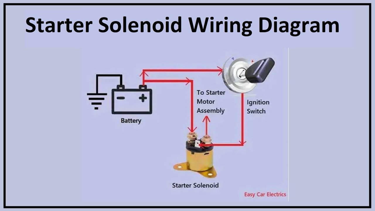
Diagram What Wires Go To The Starter Solenoid
Understanding the wiring to your starter solenoid is crucial for various automotive tasks, from diagnosing starting problems to performing engine swaps or custom wiring projects. This guide provides a detailed explanation of starter solenoid wiring diagrams, making the complex system understandable and manageable. We'll cover the key components, wiring conventions, troubleshooting, and safety considerations. Knowing this information empowers you to confidently tackle automotive electrical issues.
Purpose of Understanding Starter Solenoid Wiring
Why bother learning about this? Several scenarios make this knowledge invaluable:
- Troubleshooting Starting Problems: A common issue is a vehicle that cranks slowly or not at all. Understanding the solenoid wiring allows you to isolate whether the problem lies with the battery, starter motor, solenoid itself, or the wiring in between.
- Performing Engine Swaps or Upgrades: When swapping engines, you need to integrate the starter system with the new engine's wiring harness. Correctly wiring the solenoid is critical for proper operation.
- Custom Wiring Projects: Building a custom car or modifying an existing one often involves rewiring the starter system to accommodate aftermarket components or a cleaner aesthetic.
- General Automotive Education: Understanding the function of the starter solenoid and its wiring is a fundamental aspect of automotive electrical systems, contributing to a broader understanding of how cars work.
Key Specs and Main Parts of a Starter System
The starter system is composed of several key parts working in concert. Here's a breakdown:
- Battery: The power source for the entire electrical system, including the starter. It typically supplies 12 volts DC.
- Ignition Switch: The switch activated by the key, sending a signal to the starter solenoid when turned to the "start" position.
- Starter Solenoid: An electromagnetic switch that performs two primary functions:
- It uses a small current from the ignition switch to activate a strong magnetic field.
- This magnetic field pulls a plunger, which closes a high-current circuit connecting the battery directly to the starter motor.
- Starter Motor: A powerful electric motor that turns the engine's flywheel to initiate combustion.
- Flywheel/Flexplate: A toothed wheel connected to the engine's crankshaft. The starter motor's pinion gear engages with these teeth to turn the engine.
- Wiring Harness: The network of wires connecting all the components.
Key Specifications to Consider:
- Wire Gauge: The thickness of the wires. The starter motor circuit requires heavy-gauge wiring (typically 4 gauge or thicker) to handle the high current draw. Smaller gauge wires are used for the solenoid activation circuit.
- Voltage Rating: The voltage the components are designed to handle. In most automotive applications, this is 12V DC.
- Amperage Rating: The maximum current the solenoid can handle. This is critical to ensure the solenoid can safely handle the high current required by the starter motor.
Understanding Starter Solenoid Wiring Diagram Symbols
Wiring diagrams use standardized symbols to represent electrical components and connections. Decoding these symbols is essential for understanding the diagrams:
- Lines: Represent wires. A solid line typically indicates a standard wire, while a dashed line might indicate a shielded wire or a wire routed through a specific connector.
- Circles: Can represent various components, depending on what's inside. A circle with an "S" inside might denote the starter solenoid.
- Rectangles: Can represent components such as relays or fuses.
- Zigzag Line: Typically represents a resistor.
- Ground Symbol (usually three horizontal lines decreasing in size): Indicates a connection to the vehicle's chassis ground, which serves as the return path for the electrical circuit.
- "T" Junctions: Indicate where wires are connected. A dot at the junction confirms a connection; without a dot, the wires are simply crossing and not electrically connected.
- Color Codes: Wires are often color-coded to aid in identification. Common colors include red (power), black (ground), yellow, blue, green, and white. Refer to the specific diagram's color key for accurate identification.
Understanding Wire Colors: Wire colors aren't always consistent across manufacturers, but some common conventions exist. Always refer to the specific wiring diagram for the vehicle you are working on.
How the Starter Solenoid Wiring Works
The starter solenoid acts as an intermediary between the ignition switch and the starter motor. Here's the sequence of events:
- Key Turn: When you turn the ignition key to the "start" position, a low-current signal is sent from the ignition switch to the starter solenoid's control terminal (often labeled "S" or "Start").
- Solenoid Activation: This small current energizes the solenoid's internal coil, creating a strong magnetic field.
- Plunger Engagement: The magnetic field pulls a plunger inside the solenoid. This plunger performs two actions:
- It mechanically pushes the starter motor's pinion gear into engagement with the flywheel/flexplate teeth.
- It closes a heavy-duty electrical contact inside the solenoid, connecting the battery's positive terminal directly to the starter motor.
- Starter Motor Operation: The high-current flow from the battery to the starter motor causes the motor to spin, turning the engine.
- Key Release: When you release the key, the ignition switch signal to the solenoid is cut off. The magnetic field collapses, the plunger retracts, disengaging the pinion gear and disconnecting the battery from the starter motor.
In essence, the solenoid acts like a relay, using a small current to control a much larger current. This is necessary because the starter motor draws a significant amount of current (hundreds of amps) that the ignition switch cannot handle directly.
Real-World Use: Basic Troubleshooting Tips
Here are some basic troubleshooting tips using your understanding of starter solenoid wiring:
- No Cranking at All: Check the battery voltage first. Then, verify that the ignition switch is sending a signal to the solenoid's control terminal when the key is in the "start" position. Use a multimeter to check for voltage at the terminal. If there's no voltage, the problem may be in the ignition switch or the wiring between the switch and the solenoid.
- Clicking Sound, But No Cranking: This often indicates a weak battery or a problem with the solenoid itself. The solenoid might be engaging partially, but not able to make a good connection to supply full power to the starter motor. Check battery terminals for corrosion and clean if necessary. A load test on the battery can also help determine its condition.
- Slow Cranking: This can be caused by a weak battery, poor connections in the starter circuit (corroded terminals or loose connections), or a failing starter motor. Check the voltage drop across the starter cable while cranking; excessive voltage drop indicates high resistance in the circuit.
- Starter Stays Engaged After Releasing the Key: This is a dangerous situation and typically indicates a faulty solenoid that is stuck in the engaged position. Immediately disconnect the battery to prevent damage to the starter motor and flywheel. The solenoid needs to be replaced.
Safety Considerations
Working with automotive electrical systems can be dangerous. Here are some key safety precautions:
- Disconnect the Battery: Always disconnect the negative battery cable before working on any electrical components. This prevents accidental short circuits and potential electrical shocks.
- High Current: The starter circuit carries very high current. Avoid touching exposed terminals or wires while the engine is cranking.
- Proper Tools: Use insulated tools designed for automotive electrical work.
- Eye Protection: Wear safety glasses to protect your eyes from sparks and debris.
- Flammable Materials: Keep flammable materials away from the work area, as sparks can ignite them.
- The Starter Motor itself, when energized, can generate considerable torque. Ensure the vehicle is properly supported and stable before testing the starter system. Accidental movement could cause injury.
The Starter Solenoid's Primary High-Current Connection to the Battery is Extremely Risky: Mishandling this connection can cause significant sparks, burns, or even a fire. Always disconnect the battery before working on this circuit.
Remember...
Double-check your wiring before reconnecting the battery. Incorrect wiring can damage components and potentially create a fire hazard. It's always better to be safe than sorry.
We have the detailed starter solenoid wiring diagram file available for download, offering a comprehensive visual aid to supplement this guide. Feel free to download it and use it as a valuable resource for your automotive projects.