Diagram Where Is The Blend Door Actuator Located
Ever battled with a car that blasts scorching air on one side while freezing you on the other? Or maybe your defroster only works intermittently? Chances are, the culprit is a malfunctioning blend door actuator. Understanding its location and function is crucial for any experienced DIYer looking to tackle HVAC (Heating, Ventilation, and Air Conditioning) repairs, diagnose climate control issues, or even modify their system for improved performance. This article dives deep into the blend door actuator, providing you with the knowledge to locate it in your vehicle, understand its operation, and even troubleshoot common problems. We'll even offer a way for you to access a downloadable diagram tailored to your vehicle (check the end of the article!).
Why This Diagram Matters: Repairs, Learning, and Modification
Knowing the blend door actuator's location, functionality, and circuit is invaluable for several reasons:
- HVAC Repairs: The most common reason is diagnosing and repairing HVAC malfunctions. A faulty blend door actuator can lead to inconsistent temperatures, unresponsive climate control settings, and even complete failure of the heating or cooling system.
- System Diagnostics: Understanding the actuator's location allows you to test its functionality using a multimeter or scan tool. You can check for proper voltage, resistance, and signal input, helping you pinpoint the problem.
- System Modification: Some enthusiasts might want to modify their HVAC system for improved airflow, custom temperature zones, or even integrate aftermarket climate control systems. Knowing the actuator's location and wiring is essential for these modifications.
- Educational Purposes: Simply understanding how the system works empowers you to be a more informed car owner and make smarter decisions about your vehicle's maintenance.
Key Specs and Main Parts
The blend door actuator system, while seemingly simple, involves several key components working in harmony:
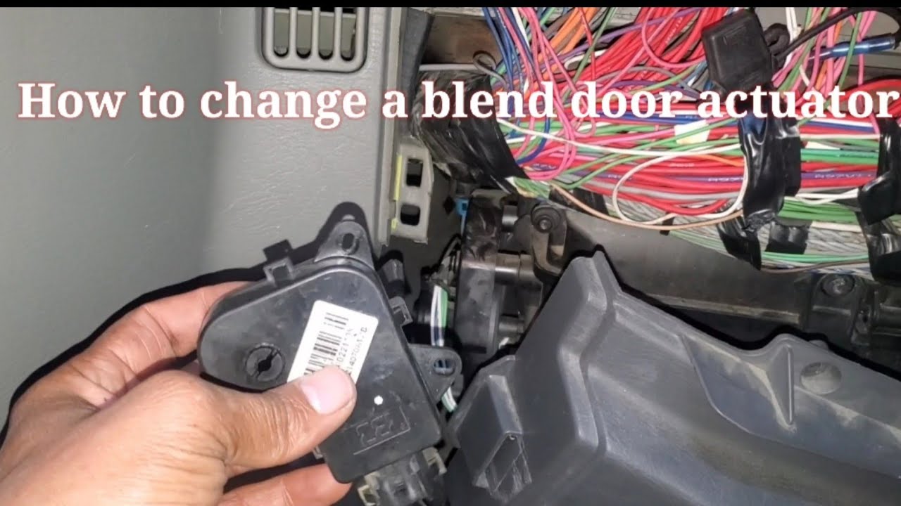
- Blend Door Actuator: This is the electric motor that physically moves the blend door. It's the heart of the system. They are typically small, rectangular plastic housings containing a DC motor, a gear train, and a position feedback sensor.
- Blend Door: This is a hinged panel located within the HVAC box. Its position determines the ratio of hot air from the heater core and cold air from the evaporator core that flows into the cabin.
- HVAC Control Module: This is the "brain" of the system. It receives input from the temperature selector knob(s) or touch screen and sends signals to the blend door actuator to adjust the blend door's position accordingly.
- Temperature Sensors: These sensors measure the temperature of the cabin, the outside air, and sometimes the air flowing through the ducts. They provide feedback to the HVAC control module to maintain the desired temperature.
- Wiring Harness: The wiring harness provides the electrical connections between all the components, allowing the HVAC control module to communicate with the actuator and sensors.
Key specs often include the operating voltage (typically 12V DC), the torque output of the motor (measured in Newton-meters or inch-pounds), and the operating temperature range.
Understanding Diagram Symbols
Electrical diagrams use a standardized set of symbols to represent different components and connections. Here's a breakdown of some common symbols you'll encounter:
- Solid Lines: Represent electrical wiring. The thickness may indicate wire gauge (thicker lines generally represent wires carrying higher current).
- Dotted Lines: Often represent shielded wiring or communication buses (like CAN bus lines).
- Resistors: A zig-zag line, representing a component that opposes the flow of electrical current.
- Capacitors: Two parallel lines, representing a component that stores electrical energy.
- Diodes: A triangle with a line at the point, representing a component that allows current to flow in only one direction.
- Ground Symbol: Usually a series of horizontal lines decreasing in size, indicating a connection to the vehicle's chassis ground.
- Actuator Symbol: Represented differently depending on the diagram; usually a rectangle or a circle with lines indicating movement. The diagram key will define this for the specific diagram.
- Color Codes: Wires are often color-coded (e.g., red for power, black for ground, blue for signal). The diagram key will specify the color code used.
Understanding these symbols is crucial for interpreting the diagram and tracing circuits.
How It Works
The HVAC system operates on a closed-loop feedback system. Here's a simplified explanation:
- The driver selects a desired temperature using the control panel.
- The HVAC control module receives this input and compares it to the readings from the temperature sensors.
- Based on this comparison, the module sends a signal to the blend door actuator.
- The actuator, powered by a small DC motor, rotates a gear train, which moves the blend door.
- The blend door regulates the mixture of hot and cold air flowing into the cabin.
- The temperature sensors continuously monitor the cabin temperature, providing feedback to the control module.
- The control module adjusts the blend door position until the desired temperature is reached and maintained.
Modern systems often use pulse-width modulation (PWM) to control the speed and position of the actuator, allowing for precise temperature control. PWM involves varying the width of an electrical pulse to control the average power delivered to the motor.
Real-World Use: Basic Troubleshooting Tips
If you suspect a blend door actuator problem, here are a few basic troubleshooting steps:
- Listen for Clicking: A rapid clicking sound coming from behind the dashboard when you adjust the temperature is often a sign of a stripped gear within the actuator.
- Check for Error Codes: Use an OBD-II scanner to check for diagnostic trouble codes (DTCs) related to the HVAC system. Common codes include those related to actuator circuit failure, position sensor failure, or actuator stuck position.
- Visual Inspection: In some cases, you may be able to visually inspect the actuator by removing a panel from under the dashboard. Look for obvious signs of damage, such as broken connectors or melted plastic.
- Multimeter Testing: With the help of the wiring diagram, you can use a multimeter to check for proper voltage and ground at the actuator connector. You can also measure the resistance of the actuator motor to check for an open or short circuit.
- Actuator Replacement: Replacing the actuator is usually straightforward. Disconnect the electrical connector, remove the mounting screws, and install the new actuator. Make sure to properly align the actuator arm with the blend door linkage.
Safety Considerations
Working on electrical systems can be dangerous if proper precautions are not taken. Here are some safety guidelines:
- Disconnect the Battery: Always disconnect the negative battery terminal before working on any electrical components. This prevents accidental short circuits and electrical shocks.
- Avoid Airbag Areas: Be extremely cautious when working near airbags. Accidental deployment can cause serious injury. If you're unsure about working near an airbag, consult a qualified technician.
- Use Proper Tools: Use insulated tools to prevent electrical shocks.
- Consult the Wiring Diagram: Always refer to the wiring diagram before attempting any electrical repairs. This will help you identify the correct wires and avoid damaging other components.
- High-Pressure Refrigerant: The HVAC system contains refrigerant under high pressure. Do not attempt to open or disconnect any refrigerant lines unless you are a qualified HVAC technician with the proper equipment. Releasing refrigerant into the atmosphere is illegal and harmful to the environment.
The blend door actuator itself is generally safe to handle, but always disconnect the battery before disconnecting any electrical connectors.
We have access to a wide range of vehicle-specific blend door actuator diagrams. To request a diagram tailored to your specific make and model, please provide us with the year, make, and model of your vehicle. We can then provide you with a downloadable diagram showing the exact location and wiring of the blend door actuator in your vehicle.