Diagrama Como Conectar Un Solenoide De Arranque
Connecting a starter solenoid correctly is crucial for getting your engine roaring to life. Whether you're replacing a faulty solenoid, undertaking an engine swap, or just trying to understand your car's electrical system better, understanding the wiring diagram is essential. This guide will walk you through the process, offering insights into the components, functions, and troubleshooting tips you'll need along the way.
Purpose of Understanding the Starter Solenoid Diagram
Why bother with a wiring diagram? There are several compelling reasons:
- Troubleshooting Starting Issues: A malfunctioning starter solenoid is a common cause of starting problems. The diagram helps you trace the circuit to identify the faulty component – whether it's the solenoid itself, a wiring problem, or even the ignition switch.
- Repairs and Replacements: When replacing a solenoid, especially on older or modified vehicles, the diagram ensures you connect the wires correctly to prevent damage to the solenoid or other electrical components.
- Engine Swaps and Custom Builds: If you're performing an engine swap or building a custom vehicle, you'll need to integrate the starter solenoid into the existing electrical system. The diagram is your roadmap.
- Understanding Vehicle Electrical Systems: Studying the starter solenoid circuit provides valuable insights into how automotive electrical systems work in general. It's a great stepping stone to understanding more complex circuits.
Key Specs and Main Parts of a Starter Solenoid System
Before diving into the diagram, let's define the key components and their specifications:
Main Components:
- Battery: The source of electrical power for the entire system. Typically, a 12V DC battery in most automotive applications.
- Ignition Switch: This switch is the first point of contact in the starting circuit. It sends power to the solenoid when turned to the "start" position.
- Starter Solenoid: This is an electromagnetic switch that controls the flow of high current to the starter motor. It has two main circuits:
- Control Circuit: A low-current circuit that energizes the solenoid's coil.
- Main Circuit: A high-current circuit that connects the battery directly to the starter motor.
- Starter Motor: The electric motor that turns the engine's flywheel (or flexplate) to initiate the combustion process. It requires a very high current.
- Wiring: High-gauge wires capable of handling the large currents required by the starter motor. Properly sized and insulated wiring is critical for safety and performance.
Key Specs to Consider:
- Voltage Rating: Usually 12V DC for automotive applications.
- Current Rating: The solenoid must be rated to handle the peak current draw of the starter motor. This can vary significantly depending on the engine size and type, but is typically 100-300 amps or more.
- Terminal Types: Common terminals include:
- Battery (+) Terminal: Connects directly to the positive terminal of the battery.
- Starter Motor Terminal: Connects to the starter motor.
- Ignition Switch Terminal: Receives power from the ignition switch.
- Ground Terminal (Optional): Some solenoids require a direct ground connection for the control circuit.
Symbols Used in Starter Solenoid Diagrams
Understanding the symbols used in the diagram is key to interpreting it correctly. Here are some common symbols you'll encounter:
- Straight Lines: Represent wires. Thicker lines typically indicate wires with higher current carrying capacity.
- Dashed Lines: May represent wires that are optional or only present in certain vehicle configurations.
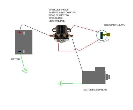
- Colors: Wires are often color-coded to help identify their function. Common colors include:
- Red: Typically indicates a power wire (positive).
- Black: Typically indicates a ground wire (negative).
- Yellow: Often used for ignition or accessory circuits.
- Blue/Green: Can be used for various control circuits.
- Battery Symbol: A series of short and long parallel lines, representing the positive and negative terminals.
- Switch Symbol: A break in a line with a lever or arrow indicating the switch mechanism.
- Solenoid Symbol: A coil symbol with a switch indicating the electromagnetic function.
- Starter Motor Symbol: A circle with an "M" inside, representing the motor.
- Ground Symbol: A series of decreasing horizontal lines, indicating a connection to the vehicle's chassis ground.
How It Works: The Starting Sequence
Here's a simplified explanation of how the starter solenoid system works:
- Turning the Key: When you turn the ignition key to the "start" position, it sends a low-current signal to the ignition switch terminal on the starter solenoid.
- Energizing the Solenoid: This signal energizes the solenoid's internal coil. This creates an electromagnetic field.
- Activating the Switch: The electromagnetic field pulls a plunger or lever inside the solenoid, closing a heavy-duty switch. This switch connects the battery directly to the starter motor.
- Spinning the Engine: The starter motor receives the high current from the battery and begins to spin the engine's flywheel (or flexplate), initiating the combustion process.
- Releasing the Key: Once the engine starts, you release the key, which de-energizes the solenoid. The switch opens, disconnecting the starter motor from the battery, and the starter motor disengages.
Real-World Use: Basic Troubleshooting Tips
Here are some common issues and troubleshooting tips related to the starter solenoid:
- Clicking Sound, No Start:
- Possible Causes: Weak battery, corroded battery terminals, faulty starter solenoid, bad starter motor, poor ground connection.
- Troubleshooting: Check battery voltage, clean battery terminals, test the solenoid (see below), test the starter motor.
- No Sound, No Start:
- Possible Causes: Faulty ignition switch, broken wire in the control circuit, bad starter solenoid.
- Troubleshooting: Check the ignition switch, trace the control circuit for continuity, test the solenoid.
- Starter Motor Cranks Slowly:
- Possible Causes: Weak battery, corroded battery terminals, high resistance in the wiring.
- Troubleshooting: Check battery voltage, clean battery terminals, inspect wiring for damage or corrosion.
Testing the Solenoid:
You can test the solenoid using a multimeter. Check for voltage at the ignition switch terminal when the key is in the "start" position. Also, check for continuity between the battery terminal and the starter motor terminal when the solenoid is energized. If the solenoid isn't passing current, it's likely faulty.
Safety: Highlighting Risky Components
Working with the starter solenoid system involves high currents and potentially dangerous voltages. Always disconnect the negative battery cable before working on any electrical components. The starter motor circuit carries a significant amount of amperage and a short circuit can quickly lead to fire or severe burns. Be especially careful when working with the large-gauge wires connected to the battery and starter motor. Inspect these wires regularly for damage and replace them if necessary. Incorrect wiring can also cause damage to the solenoid itself, the starter motor, or other parts of the electrical system. If you are unsure about any aspect of the repair, consult a qualified mechanic.
Remember that improper handling of electrical components, especially those dealing with high amperage, can result in serious injury. Always follow proper safety precautions and consult with a qualified professional if you are unsure about any aspect of the repair or troubleshooting process.
We have a detailed starter solenoid wiring diagram file available for download. This diagram will provide a visual aid to complement the information outlined in this article, making your repair or upgrade project more efficient and safe.