Diagrama Cuerpo De Aceleracion Partes
For the experienced DIYer tackling engine work, understanding the throttle body diagram, or Diagrama Cuerpo De Aceleracion in Spanish, is crucial. It's not just a pretty picture; it's a roadmap to diagnosing issues, performing maintenance, and even modifying your engine's air intake system. This guide will break down the diagram's key components, explain how it works, and provide some real-world troubleshooting tips. Consider this your deep dive into the inner workings of your throttle body. We also provide the file for you to download at the end of this article.
Purpose: Why a Throttle Body Diagram Matters
The throttle body diagram is more than just a schematic; it's an essential tool for several reasons:
- Troubleshooting: When your engine exhibits symptoms like rough idling, poor acceleration, or stalling, the throttle body is often a prime suspect. The diagram helps you pinpoint the faulty component, whether it's a sensor, actuator, or a vacuum leak.
- Maintenance: Routine cleaning and inspection of the throttle body can prevent performance issues. The diagram allows you to identify all the parts you need to access and clean, ensuring a thorough job.
- Modifications: If you're planning to upgrade your air intake system or modify your engine's performance, understanding the throttle body's design is critical. The diagram helps you determine compatibility and identify potential bottlenecks.
- Repair and Replacement: If a throttle body component fails, the diagram helps you identify the correct replacement part and understand how to install it properly.
- Understanding Engine Operation: Even if you're not actively working on your car, studying the throttle body diagram provides valuable insight into how your engine regulates airflow and fuel mixture.
Key Specs and Main Parts
Throttle bodies vary in design depending on the engine type, manufacturer, and year. However, some core components are universal:
Main Components:
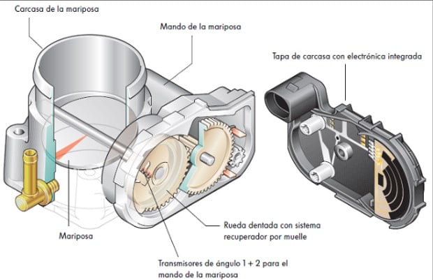
- Throttle Plate (Valve): This is the heart of the throttle body. It's a butterfly valve that pivots to control the amount of air entering the intake manifold. Its angle, usually measured by the Throttle Position Sensor, directly impacts the engine's power output.
- Throttle Shaft: The throttle plate is attached to the throttle shaft, which rotates to open and close the plate.
- Throttle Position Sensor (TPS): The TPS is a potentiometer that measures the throttle plate's angle and sends this information to the engine control unit (ECU). The ECU uses this data to adjust fuel injection and ignition timing.
- Idle Air Control (IAC) Valve/Motor: The IAC valve (or motor in newer systems) regulates the amount of air that bypasses the throttle plate when it's closed. This maintains a stable idle speed. The IAC valve is crucial for smooth engine operation at idle and during deceleration.
- Throttle Cable/Electronic Throttle Control (ETC) Motor: In older vehicles, a throttle cable connects the accelerator pedal directly to the throttle shaft. In newer vehicles with ETC (also known as "drive-by-wire"), an electric motor controls the throttle plate based on signals from the accelerator pedal position sensor.
- Vacuum Ports: These small ports connect to various vacuum lines that control other engine components, such as the EGR valve (Exhaust Gas Recirculation) or the fuel pressure regulator.
- Coolant Passages (Sometimes): Some throttle bodies have coolant passages to prevent icing in cold weather. This is particularly common in areas with high humidity and low temperatures.
Key Specs:
- Bore Size: The diameter of the throttle body opening. A larger bore size generally allows for more airflow, potentially increasing engine power.
- Flow Rate (CFM): Cubic Feet per Minute. This measures the volume of air the throttle body can flow at a specific pressure drop. Higher CFM generally means more power potential.
- TPS Voltage Range: The TPS outputs a voltage that varies with the throttle plate angle. The voltage range is critical for proper ECU operation. Typical range is 0.5V at closed throttle to 4.5V at wide open throttle.
- IAC Valve Resistance: If your car uses an IAC valve, its resistance can be measured with a multimeter to check for proper operation.
Symbols: Lines, Colors, and Icons
Throttle body diagrams use a standardized set of symbols to represent different components and connections. Understanding these symbols is essential for interpreting the diagram correctly:
- Solid Lines: Typically represent mechanical connections, such as the throttle cable linkage or the physical body of the throttle body itself.
- Dashed Lines: Usually indicate vacuum lines or other low-pressure connections.
- Dotted Lines: May represent electrical wiring or other signal paths.
- Colors: While not universally standardized, colors can be used to differentiate between different types of lines or components. For example, a red line might represent a power wire, while a blue line might represent a sensor signal wire.
- Icons: Specific icons are used to represent components like sensors, actuators, and connectors. A square with a diagonal line might represent a resistor, while a circle with an arrow might represent a sensor.
Pay attention to the legend or key provided with the diagram, as it will explain the specific symbols and colors used in that particular diagram.
How It Works
The throttle body's primary function is to regulate the amount of air entering the engine. Here's a breakdown of the process:
- Accelerator Pedal Input: The driver presses the accelerator pedal, which either pulls on the throttle cable (in older vehicles) or sends a signal to the ECU via the accelerator pedal position sensor (in newer vehicles).
- Throttle Plate Control: In a cable-operated system, the throttle cable directly rotates the throttle shaft, opening the throttle plate. In an ETC system, the ECU controls an electric motor that rotates the throttle shaft.
- Airflow Regulation: As the throttle plate opens, more air enters the intake manifold. The amount of air entering is directly proportional to the throttle plate angle.
- Sensor Feedback: The TPS monitors the throttle plate angle and sends this information back to the ECU. This allows the ECU to adjust fuel injection and ignition timing to match the airflow.
- Idle Air Control: When the throttle plate is closed, the IAC valve allows a small amount of air to bypass the throttle plate, maintaining a stable idle speed. The ECU controls the IAC valve to adjust the idle speed based on engine load and temperature.
The ECU constantly monitors various sensors and adjusts the throttle plate position, fuel injection, and ignition timing to optimize engine performance and efficiency.
Real-World Use: Basic Troubleshooting Tips
Here are some common problems related to the throttle body and how the diagram can help you diagnose them:
- Rough Idling: A dirty throttle body or a malfunctioning IAC valve can cause rough idling. The diagram can help you locate the IAC valve and identify the vacuum lines that need to be checked for leaks. Use throttle body cleaner to clean any carbon deposits.
- Poor Acceleration: A faulty TPS or a restricted airflow due to a dirty air filter can cause poor acceleration. The diagram helps you locate the TPS and check its voltage output with a multimeter.
- Stalling: A vacuum leak in the throttle body or a malfunctioning IAC valve can cause the engine to stall. The diagram helps you identify all the vacuum ports and check them for leaks. You can use carb cleaner, spray on the suspected areas, and listen for engine RPM changes to find the leak source.
- Check Engine Light (CEL): Various throttle body-related issues can trigger the CEL. Use an OBD-II scanner to read the trouble codes and then refer to the diagram to troubleshoot the specific component.
Example: If you get a P0121 code (Throttle Position Sensor A Circuit Range/Performance), the diagram will help you locate the TPS, check its wiring, and test its voltage output. You can compare the output voltage with the manufacturer's specifications to determine if the TPS is faulty.
Safety: Highlight Risky Components
Working on the throttle body involves some safety considerations:
- Electrical Components: Disconnect the negative battery terminal before working on any electrical components, such as the TPS or IAC valve.
- Moving Parts: Be careful when working around the throttle plate and linkage, as they can move unexpectedly.
- Hot Surfaces: The throttle body can get hot during engine operation. Allow the engine to cool down before working on it.
- Flammable Liquids: Use caution when working with throttle body cleaner or other flammable liquids. Avoid sparks or open flames.
- Electronic Throttle Control (ETC) Systems: Exercise extreme caution when working on ETC systems. Improper handling can damage the throttle body or the ECU. In some cases, professional assistance is recommended.
Important Note: Always consult your vehicle's repair manual for specific instructions and safety precautions. If you're not comfortable working on your car, it's best to take it to a qualified mechanic.
With the right knowledge and tools, you can successfully troubleshoot and maintain your throttle body using the diagram as your guide. Remember to always prioritize safety and consult your vehicle's repair manual for specific instructions.
Click here to download the Throttle Body Diagram file: [Download Link Here - Placeholder]