Diagrama De Conexion Estereo Clarion Nissan
Alright, let's dive into the wiring diagram for a Clarion stereo in a Nissan vehicle. This isn't just some abstract piece of paper; it's the roadmap to understanding how your car's audio system is wired. Whether you're planning an upgrade, diagnosing a problem, or just curious about how it all connects, grasping this diagram is crucial. We’ll cover the purpose, key specs, how to read it, and even some real-world troubleshooting tips. And the best part? We have the file you need, ready for download after you've absorbed this knowledge.
Purpose of the Clarion/Nissan Stereo Wiring Diagram
Why bother with a wiring diagram? Simple: it's your single source of truth when working with your car's audio system. Specifically, the Clarion/Nissan stereo wiring diagram serves several essential purposes:
- Repair and Troubleshooting: When your stereo isn't working correctly – no power, distorted sound, or speakers cutting out – the diagram helps you trace the signal path and identify the faulty component.
- Upgrades and Modifications: Planning to install a new amplifier, subwoofer, or even a different head unit? The diagram shows you where to tap into the existing wiring and ensures a clean, safe installation.
- Understanding System Function: Even if you don't plan on modifying anything, the diagram helps you understand how all the components work together, from the head unit to the speakers and antenna.
- Preventing Damage: Guessing with electrical wiring is a recipe for disaster. Using the diagram minimizes the risk of short circuits, blown fuses, and damaged equipment.
Key Specs and Main Parts
Before we dissect the diagram itself, let's identify the core components involved. These will be clearly represented on the diagram, and knowing what they are is half the battle:
Main Components:
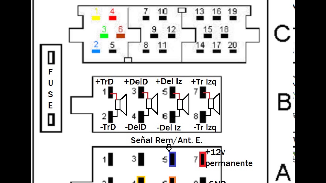
- Head Unit (Stereo): This is the brains of the operation. It receives signals from various sources (radio, CD, Bluetooth) and outputs amplified audio signals to the speakers. Pay close attention to the pinout diagram for the head unit connector – it's critical.
- Speakers: Typically, you'll have four or more speakers: front left, front right, rear left, and rear right. The diagram will show the wire colors and polarity (+/-) for each speaker.
- Antenna: The antenna receives radio signals. The diagram will show the connection point for the antenna cable.
- Power Supply: The stereo needs power to operate. The diagram shows the connections for 12V constant (for memory), 12V switched (ignition-controlled), and ground.
- Ground (Chassis Ground): A solid ground connection is crucial for proper operation and preventing noise. The diagram will show the grounding point.
- Fuses: Fuses protect the stereo and your car's electrical system from overcurrent. The diagram may indicate the location and amperage of the relevant fuse.
Key Specifications:
- Voltage: Almost always 12V DC in modern vehicles.
- Speaker Impedance: Usually 4 ohms. Using speakers with the wrong impedance can damage the amplifier in the head unit.
- Wire Gauge: The thickness of the wires. Thicker wires can handle more current.
- Polarity: The positive (+) and negative (-) connections for each speaker. Incorrect polarity can result in poor sound quality, specifically cancellation of bass frequencies.
Understanding the Diagram: Symbols, Lines, and Colors
The wiring diagram is essentially a symbolic language. Here's how to decipher it:
Lines:
- Solid Lines: Represent wires. Thicker lines might indicate a higher current-carrying capacity.
- Dashed Lines: Can represent shielded cables or optional connections. They may also represent circuits located on a separate schematic.
- Arrows: Indicate the direction of current flow.
Colors:
Each wire is assigned a color code, which is crucial for identifying the correct wires in your car. Common colors include:
- Red: Typically 12V constant (battery power).
- Yellow: Typically 12V switched (ignition power).
- Black: Ground.
- White, Gray, Green, Purple: Usually speaker wires, often with a stripe of another color to differentiate left and right channels or positive and negative terminals. For example: White/Black could indicate left front positive, where solid White indicates left front negative.
Always double-check the color codes against the diagram. Color codes can vary slightly depending on the year and model of the Nissan vehicle.
Symbols:
- Ground Symbol: Looks like an upside-down Christmas tree or a series of decreasing horizontal lines.
- Fuse Symbol: A zigzag line inside a rectangle.
- Speaker Symbol: Resembles a loudspeaker.
- Connector Symbol: Often a circle or square with pins indicated. These are crucial for identifying the correct wires at the back of the head unit.
The diagram will also typically include annotations, short text labels that describe the function of each wire or component. Take your time and read these carefully!
How It Works: Tracing the Signal
Understanding how the stereo system works requires tracing the signal flow on the diagram. Here’s a simplified breakdown:
- Power Input: 12V constant and 12V switched power enter the head unit. The 12V constant keeps the memory alive (presets, clock), while the 12V switched turns the stereo on and off with the ignition.
- Signal Input: The head unit receives signals from the antenna (radio), CD player (if equipped), or external devices (through auxiliary input or Bluetooth).
- Signal Processing: The head unit processes these signals, allowing you to adjust volume, tone, and balance.
- Amplification: The head unit's internal amplifier boosts the audio signal.
- Speaker Output: The amplified audio signal is sent to the speakers via the speaker wires.
- Ground: All electrical components require a solid ground connection to complete the circuit.
By following these steps on the diagram, you can understand how each component contributes to the overall audio experience.
Real-World Use: Basic Troubleshooting Tips
Now that you understand the diagram, let's put it to use with some basic troubleshooting scenarios:
- No Power: Check the fuses first. Use a multimeter to verify that you have 12V constant and 12V switched power at the head unit connector. Also, ensure that the ground connection is secure.
- No Sound from One Speaker: Check the speaker wiring for that specific speaker. Use a multimeter to test the speaker itself to ensure it's not blown. You can also try swapping the speaker with a known working speaker to isolate the issue.
- Distorted Sound: Check the speaker impedance. Ensure that the speakers are rated for the correct impedance for the head unit. Also, check for loose or corroded connections.
- Interference or Noise: Check the ground connection. A poor ground can introduce noise into the audio signal. Also, ensure that the antenna cable is properly connected and shielded.
Always disconnect the battery before working on any electrical components to prevent short circuits and electrical shock.
Safety Considerations
Working with car electronics can be dangerous if you're not careful. Here are some critical safety precautions:
- Disconnect the Battery: This is the most important safety step. Disconnect the negative terminal of the battery before working on any electrical components.
- Use Proper Tools: Use insulated tools to prevent short circuits.
- Identify Wires Correctly: Double-check the wiring diagram before cutting or splicing any wires.
- Protect Your Eyes: Wear safety glasses to protect your eyes from debris.
- Work in a Well-Ventilated Area: Avoid working in confined spaces where fumes can accumulate.
Risky Components: The power wires (12V constant and 12V switched) carry a significant amount of current. Be extremely careful when working with these wires to avoid short circuits. Incorrect wiring can damage your car's electrical system or even start a fire.
Get the Diagram
Hopefully, this has given you a solid foundation for understanding the Clarion stereo wiring diagram for your Nissan vehicle. Remember, patience and attention to detail are key to success. Now that you're armed with this knowledge, you're ready to tackle your audio project with confidence.
As promised, we have the full wiring diagram available for download. This detailed diagram will provide even more specific information about your particular Nissan model and Clarion stereo. Having it on hand will be invaluable for repairs, upgrades, and general understanding of your car's audio system.
Good luck, and happy listening!