Diagrama De Fusibles Nissan Frontier 2015
Alright, let's dive into the fuse diagram for your 2015 Nissan Frontier. This isn't just some pretty picture; it's your roadmap to electrical troubleshooting and repair. Understanding it can save you a ton of time, money, and frustration, whether you're fixing a blown tail light, diagnosing a parasitic draw, or adding aftermarket accessories.
Purpose of the Fuse Diagram
The fuse diagram is essentially a key that unlocks the electrical system of your Frontier. Its primary purpose is to show you the location of each fuse and relay, and, most importantly, what circuit each protects. Think of fuses as tiny sacrificial lambs. They're designed to blow, or open the circuit, when there's an overload or short circuit. This prevents damage to more expensive components like the ECU (Engine Control Unit), lights, sensors, and wiring harnesses. Without a fuse diagram, you're essentially guessing which fuse controls what, leading to potentially wasted time and further electrical problems.
Beyond repairs, a fuse diagram is also invaluable for those of you who like to modify your trucks. Want to add a light bar? You'll need to tap into an existing circuit or run a new one with its own fuse. The diagram helps you identify suitable circuits and choose the correct fuse amperage to protect your new accessory and your truck's electrical system.
Key Specs and Main Parts of the Fuse Diagram
Before we start dissecting the diagram, let's talk about what you'll typically find on a 2015 Nissan Frontier fuse layout. It's crucial to note that depending on your trim level (S, SV, PRO-4X, etc.) and options, the fuse layout might have slight variations. Always refer to the diagram specifically for your truck.
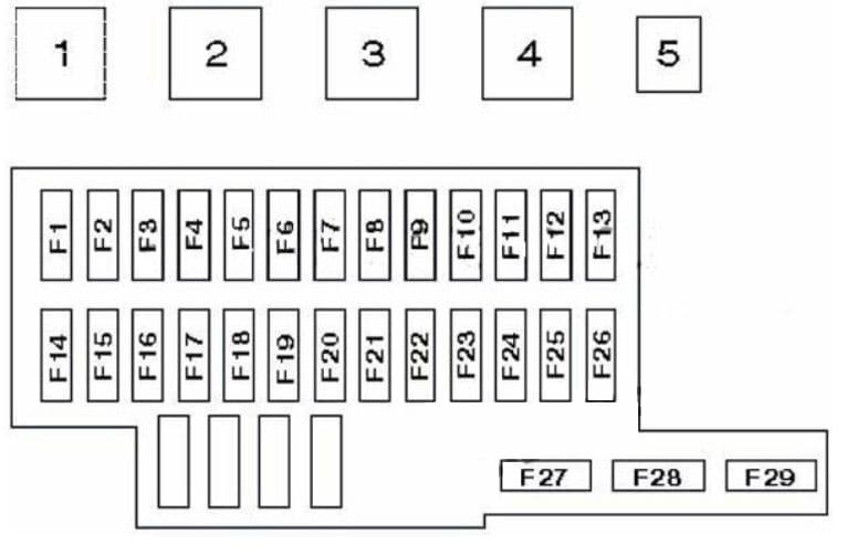
- Fuse Boxes/Panels: Your Frontier likely has at least two fuse boxes. One is usually located under the dashboard, often near the driver's side kick panel. The other is typically found in the engine compartment, near the battery. Some models may have a third fuse box, located elsewhere in the engine bay.
- Fuses: These are the small, color-coded components that protect the circuits. They come in different amperage ratings, indicated by the number printed on them (e.g., 5A, 10A, 15A, 20A, 30A). The color of the fuse also corresponds to its amperage rating, making it easier to identify them quickly. Common fuse types include blade fuses (ATO/ATC) and mini blade fuses.
- Relays: Relays are electromechanical switches that control high-current circuits using a low-current signal. They're used for things like headlights, fuel pump, and starter motor. The fuse diagram will show the location of each relay and the circuit it controls.
- Diagram Legend: This is the most important part! The legend explains the symbols, abbreviations, and fuse/relay assignments. Without the legend, the diagram is just a bunch of confusing lines and boxes.
Understanding Fuse Diagram Symbols
Navigating a fuse diagram involves understanding the symbols used to represent different components and connections. Here's a breakdown of some common symbols you'll encounter:
- Solid Lines: Represent wiring. Thicker lines generally indicate wires carrying higher current.
- Dashed Lines: Often indicate ground connections or signal wires.
- Boxes: Represent fuses or relays. The amperage rating is usually indicated inside the box for fuses.
- Circles: Can represent various components, depending on the specific symbol and legend. They could indicate connectors, sensors, or other electrical devices.
- Color Coding: Wire colors are often indicated on the diagram using abbreviations (e.g., "BL" for blue, "RD" for red, "BK" for black). Following the wire colors helps trace circuits.
- Icons: Specific icons are used to represent the function of the circuit protected by a particular fuse. Examples include a light bulb for lighting circuits, a fan for cooling fan circuits, a steering wheel for power steering, etc. The legend will define each icon.
Pay close attention to the legend. It's your Rosetta Stone for deciphering the diagram.
How It Works: Tracing a Circuit
Let's say your cigarette lighter/power outlet isn't working. Here's how you'd use the fuse diagram to diagnose the problem:
- Consult the Fuse Diagram: Locate the diagram for your 2015 Frontier. Consult the owner’s manual first as it may contain the fuse diagrams. If not, you will need the factory service manual (FSM). Once you have the correct fuse diagram, find the fuse specifically labeled for the "cigarette lighter" or "power outlet". It will likely be in the interior fuse box.
- Identify Fuse Location and Amperage: The diagram will show the fuse's location within the fuse box and its amperage rating (e.g., 15A).
- Inspect the Fuse: Physically locate the fuse in the fuse box. Use a fuse puller (usually included in the fuse box) to remove the fuse. Examine the fuse element. If it's broken or blackened, the fuse is blown.
- Test the Circuit (Optional): Before replacing the fuse, it's a good idea to test the circuit for a short. Use a multimeter to check for continuity between the power outlet terminals and ground. If there's continuity, there's a short circuit that needs to be addressed before replacing the fuse.
- Replace the Fuse: Replace the blown fuse with a new fuse of the same amperage rating. Never use a higher amperage fuse, as this could damage the wiring or other components.
- Test the Power Outlet: Turn on the ignition and test the power outlet to see if it's working.
Real-World Use: Basic Troubleshooting Tips
Here are some practical troubleshooting tips using the fuse diagram:
- Blown Fuses: If a fuse blows repeatedly, it indicates a problem in the circuit. Don't just keep replacing the fuse. You need to find the underlying cause, which could be a short circuit, a faulty component, or an overloaded circuit.
- Parasitic Draw: If your battery keeps dying overnight, you might have a parasitic draw – something is draining power even when the ignition is off. The fuse diagram can help you isolate the circuit causing the draw. Remove fuses one at a time and monitor the current draw using a multimeter. When the current drops significantly, you've found the circuit with the problem.
- Adding Accessories: When adding aftermarket accessories, always use a fuse tap (also known as an add-a-circuit) to tap into an existing circuit. Use the fuse diagram to identify a suitable circuit with the appropriate amperage rating. Make sure the accessory is properly grounded.
Safety Considerations
Working with electrical systems can be dangerous. Here are some important safety precautions:
- Disconnect the Battery: Before working on any electrical components, disconnect the negative battery terminal. This will prevent accidental shorts and shocks.
- Never Bypass a Fuse: Never use a piece of wire or other conductive material to replace a fuse. This bypasses the protection mechanism and could cause a fire or damage electrical components.
- Use the Correct Amperage Fuse: Always replace a blown fuse with a fuse of the same amperage rating. Using a higher amperage fuse could overload the circuit and cause a fire.
- Be Careful Around the Airbag System: The airbag system is a sensitive and potentially dangerous system. If you're working near the airbag control module or any airbag components, take extra precautions to avoid accidental deployment. Consult the service manual for specific safety instructions. The airbag system fuses should be handled with extreme caution. A sudden power surge or miswiring can cause accidental deployment.
Specifically, the SRS (Supplemental Restraint System - Airbag) circuit and the ABS (Anti-lock Braking System) circuit are very critical. Do not tamper with these fuses unless you absolutely know what you are doing. Improper handling can lead to airbag malfunction, accidental deployment, or ABS failure, all of which can have serious safety consequences.
Disclaimer: This information is for general guidance only. Always consult the factory service manual for your specific vehicle before performing any repairs or modifications. Electrical systems can be complex, and improper handling can lead to damage or injury.
We have the 2015 Nissan Frontier fuse diagram readily available. Reach out to us, and we'll provide you with a downloadable copy to assist in your troubleshooting and maintenance endeavors.