Diagrama Sensores De Transmision Automatica Dodge Caravan
So, you're looking at the transmission sensors on your Dodge Caravan. Good on you for digging in! Understanding these sensors and how they're wired is crucial for diagnosing transmission problems, performing repairs, or even undertaking some cool modifications. This article will walk you through a typical wiring diagram for these sensors, giving you the knowledge to tackle those tasks with confidence. We even have the full diagram file available for download later on.
Purpose of the Transmission Sensor Diagram
Why bother with a wiring diagram? Several reasons. First and foremost, it's your roadmap for diagnosing transmission issues. When your check engine light pops on and you get a transmission-related code (like a P0700 series code), the diagram helps you pinpoint the problematic sensor or its wiring. It allows you to trace the circuit, check for voltage, continuity, and shorts, ultimately leading to a faster and more accurate diagnosis. Without the diagram, you're essentially guessing, which can lead to unnecessary parts replacements and wasted time. This is especially helpful with intermittent issues that come and go.
Second, the diagram is indispensable for repairs. Let's say you're replacing a damaged sensor connector or repairing a cut wire. The diagram shows you exactly which wire goes where, preventing accidental miswiring that could cause further damage. Finally, for those interested in modifying their transmission (like adding a shift kit or aftermarket controller), the diagram provides the necessary information to integrate new components safely and effectively.
Key Specs and Main Parts
A typical Dodge Caravan automatic transmission relies on several key sensors to monitor its operation. These sensors provide crucial data to the Transmission Control Module (TCM), which uses this information to control shift timing, torque converter lockup, and overall transmission performance. The specific sensors can vary slightly depending on the year and model, but common ones include:
- Input Shaft Speed Sensor (ISS): This sensor monitors the speed of the input shaft, which is directly connected to the engine. It's usually a variable reluctance sensor, meaning it generates an AC voltage signal that varies with the shaft speed. This data helps the TCM determine the engine's input to the transmission.
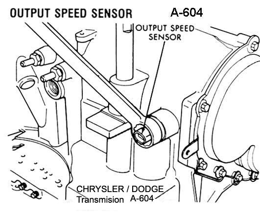
- Output Shaft Speed Sensor (OSS): This sensor monitors the speed of the output shaft, which is connected to the wheels. Like the ISS, it's typically a variable reluctance sensor. The TCM uses OSS data to calculate the vehicle's speed and determine the appropriate shift points.
- Transmission Fluid Temperature (TFT) Sensor: This sensor measures the temperature of the transmission fluid. It's usually a thermistor, meaning its resistance changes with temperature. The TCM uses TFT data to adjust shift patterns and torque converter lockup, especially in extreme temperatures. Overheating is a transmission killer, so this sensor is vital.
- Transmission Range Sensor (TRS) / Park/Neutral Position (PNP) Switch: This sensor indicates the gear selector position (Park, Reverse, Neutral, Drive, etc.). It sends a signal to the TCM indicating the selected gear, which is crucial for starting the engine and engaging the correct gear ratio. It's often a multi-position switch with several contacts that are activated in different positions.
- Solenoids: These are not technically sensors, but they are critical components controlled by the TCM based on sensor inputs. Shift solenoids control the flow of fluid to different hydraulic circuits within the transmission, enabling gear changes. Torque converter clutch (TCC) solenoids control the engagement and disengagement of the torque converter lockup clutch.
Important specifications you might encounter include sensor resistance values (typically measured in ohms), voltage ranges (usually 0-5V or 0-12V), and the type of connector used (e.g., 3-pin, 4-pin). Knowing these specs helps you verify the sensor's functionality using a multimeter.
Understanding Diagram Symbols
Wiring diagrams use a standardized set of symbols to represent components and connections. Here's a breakdown of the most common ones you'll encounter in a transmission sensor diagram:
- Lines: Solid lines represent wires. Thicker lines might indicate power or ground wires. Dashed lines often indicate shielded wires (used for sensors that are sensitive to electromagnetic interference).
- Colors: Each wire is color-coded. Common colors include red (power), black (ground), and various other colors for signal wires. The diagram will usually have a legend explaining the color codes. Knowing the colors allows you to physically identify the correct wire in the harness.
- Circles: Circles often represent connectors. The numbers inside the circle indicate the pin number.
- Rectangles: Rectangles typically represent components like the TCM, sensors, or solenoids. Inside the rectangle, you'll find the component's name or abbreviation.
- Ground Symbols: Different ground symbols exist, but they all indicate a connection to the vehicle's chassis ground.
- Resistors: A zig-zag line represents a resistor.
- Arrows: Arrows can indicate the direction of current flow.
Pay close attention to the wire gauges (indicated by a number followed by AWG - American Wire Gauge). Using the wrong gauge wire can lead to overheating and electrical problems. Also, understand the difference between a series circuit (components connected one after another) and a parallel circuit (components connected side-by-side).
How It Works: The Sensor Data Flow
The TCM is the brain of the transmission. It receives data from the various sensors, processes that data, and then sends commands to the solenoids to control shifting and torque converter lockup. Here's a simplified overview of the process:
- The Input Shaft Speed Sensor (ISS) and Output Shaft Speed Sensor (OSS) send speed signals to the TCM.
- The Transmission Fluid Temperature (TFT) sensor sends temperature data to the TCM.
- The Transmission Range Sensor (TRS) indicates the selected gear.
- The TCM analyzes this data in conjunction with other inputs (e.g., engine speed, throttle position).
- Based on its programming, the TCM determines the optimal shift point and torque converter lockup state.
- The TCM sends signals to the appropriate shift solenoids and the torque converter clutch (TCC) solenoid.
- The solenoids actuate, directing fluid to the correct hydraulic circuits, causing the transmission to shift or the torque converter to lock up.
This is a closed-loop system. The TCM constantly monitors the sensor data and adjusts the solenoids as needed to maintain optimal transmission performance. Any disruption in this data flow (e.g., a faulty sensor, a broken wire) can lead to transmission problems.
Real-World Use: Basic Troubleshooting
Let's say you have a code indicating a problem with the Output Shaft Speed Sensor (OSS). Here's how you can use the wiring diagram to troubleshoot the issue:
- Locate the OSS on the diagram. Identify the sensor, its connector, and the wires leading to the TCM.
- Identify the wire colors and pin numbers. This will help you locate the correct wires in the vehicle's wiring harness.
- Check for voltage at the sensor connector. Use a multimeter to verify that the sensor is receiving power and ground. The diagram will indicate the expected voltage levels.
- Check for continuity between the sensor connector and the TCM. Disconnect the battery and use a multimeter to check for continuity on each wire. This verifies that the wires are not broken or shorted to ground.
- Check the sensor's resistance. Disconnect the sensor and use a multimeter to measure its resistance. Compare the measured value to the manufacturer's specifications.
If you find a problem with the wiring (e.g., a broken wire, a short to ground), repair or replace the affected wire. If the sensor itself is faulty (e.g., incorrect resistance), replace the sensor. Remember to clear the trouble codes after making repairs.
Safety Precautions
Working with automotive electrical systems can be dangerous. Always disconnect the negative battery cable before working on any electrical components. Be especially careful when working around the TCM and the transmission itself, as these components can contain high voltages and hot fluids. When checking for voltage, use a multimeter with insulated probes and wear safety glasses. Avoid working under the vehicle unless it is securely supported by jack stands. Never rely solely on a jack.
Be extremely careful when working around the transmission fluid. It can be very hot and caustic. Wear gloves and eye protection. Additionally, some sensors, like the Park/Neutral Position switch can affect starting safety. Always ensure the car is in park and the parking brake is engaged before working on this part.
Disclaimer: Always consult the vehicle's service manual for specific instructions and safety precautions. This information is for educational purposes only and should not be substituted for professional advice.
We have the complete wiring diagram file for the Dodge Caravan transmission sensors. You can download it here. This diagram will provide you with even more detailed information and specific wiring configurations for your vehicle.