Distributor Cap Chevy 305 Firing Order Diagram
The distributor cap on a Chevy 305 engine, and the firing order diagram associated with it, are crucial for ensuring the engine runs smoothly and efficiently. Understanding this system is vital for various tasks, from basic tune-ups and diagnosing misfires to more complex engine modifications and troubleshooting. This article will break down the intricacies of the distributor cap and its firing order diagram, offering a comprehensive guide for the intermediate car enthusiast or DIY mechanic.
Purpose of the Firing Order Diagram
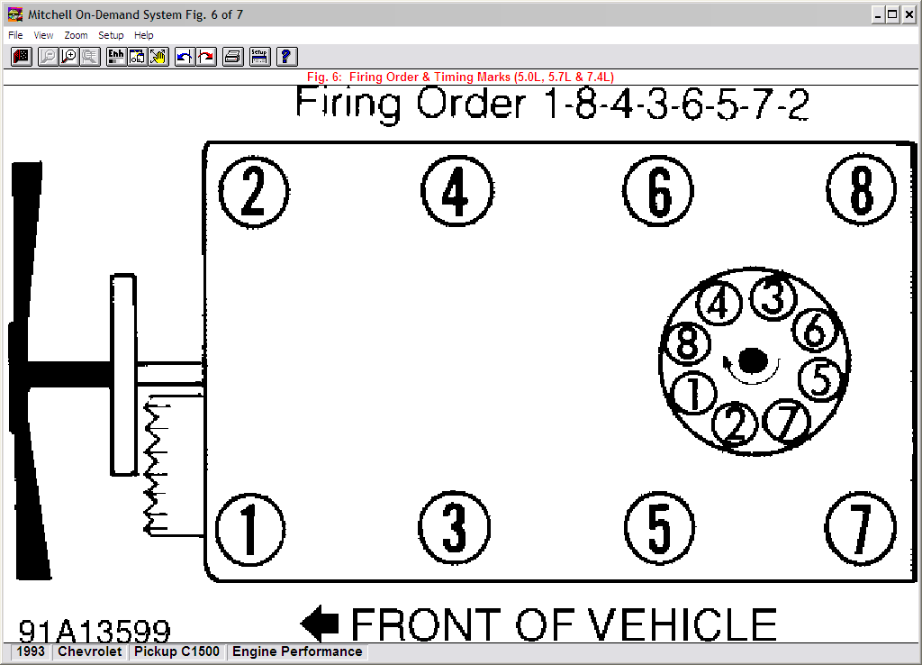
The firing order diagram is your roadmap to a properly firing engine. Its primary purpose is to show the correct sequence in which the spark plugs should fire within the cylinders. The Chevy 305 firing order is 1-8-4-3-6-5-7-2. Without this sequence, combustion will be erratic, leading to misfires, rough idling, reduced power, and potentially even engine damage. A firing order diagram is essential for:
- Tune-ups: Ensuring the spark plug wires are connected to the correct terminals on the distributor cap during routine maintenance.
- Troubleshooting Misfires: Identifying if a wire is connected incorrectly or if a cylinder isn't firing in the correct sequence.
- Engine Swaps and Modifications: Verifying the distributor is properly aligned and the firing order is correct after major engine work.
- Learning Engine Mechanics: Grasping the fundamental principles of internal combustion and distributor function.
Key Specs and Main Parts
Before diving into the diagram, let's familiarize ourselves with the key components:
Distributor Cap
The distributor cap is a protective cover made of a high-strength, non-conductive plastic. Its function is to distribute the high-voltage electricity from the ignition coil to the spark plugs in the correct firing order. Key features include:
- Terminals: Eight terminals (one for each cylinder in a V8 engine like the 305) that connect to the spark plug wires.
- Center Terminal: A single terminal in the center that receives the high-voltage current from the ignition coil.
- Rotor: A rotating arm inside the distributor cap that makes contact with each terminal in sequence, distributing the spark.
- Vent(s): Small openings that allow moisture and ozone buildup to escape, preventing corrosion and electrical arcing.
Spark Plug Wires
These wires carry the high-voltage electricity from the distributor cap terminals to the spark plugs. They are designed to withstand extremely high voltages (tens of thousands of volts) and must be properly insulated to prevent electrical leaks.
Spark Plugs
The spark plugs ignite the air-fuel mixture within the cylinders, initiating the combustion process. They are located in the cylinder head and must be in good condition to ensure proper ignition.
Ignition Coil
The ignition coil is an induction coil in the ignition system that transforms the battery's low voltage to the thousands of volts needed to create an electric spark in the spark plugs to ignite the fuel. It sends the high-voltage pulse to the distributor.
Understanding the Firing Order Diagram Symbols
A typical firing order diagram for a Chevy 305 visually represents the distributor cap and the corresponding cylinder numbers. Common symbols and conventions include:
- Distributor Cap Outline: A circular or semi-circular representation of the distributor cap, showing the location of each terminal.
- Cylinder Numbers: Numbers (1 through 8 for a V8 engine) indicating which cylinder each terminal connects to. The Chevy 305 firing order is 1-8-4-3-6-5-7-2.
- Lines: Lines connect each terminal on the distributor cap to the corresponding cylinder number, clearly illustrating the firing order sequence. These lines can be a single color or have alternating colors to help differentiate between wires.
- Rotor Direction: An arrow indicating the direction of rotation of the distributor rotor. This is typically clockwise for most Chevy engines.
- Engine Orientation: Some diagrams might include a simplified drawing of the engine block, showing the cylinder locations (left and right banks). Understanding the engine bank numbering is crucial for proper wire placement. Typically, the cylinders are numbered 1, 3, 5, 7 on one bank, and 2, 4, 6, 8 on the other bank.
There are no standard colors. However, it’s important to follow your diagram meticulously.
How It Works: The Ignition Process
The ignition process starts with the battery providing power to the ignition coil. The ignition coil then boosts the voltage significantly (typically to 20,000-40,000 volts). This high-voltage current is sent to the center terminal of the distributor cap. Inside the distributor, the rotor spins, making contact with each terminal on the cap in a specific sequence dictated by the firing order. As the rotor contacts a terminal, the high-voltage current is sent through the corresponding spark plug wire to the spark plug in that cylinder. The spark plug then ignites the air-fuel mixture, initiating combustion and driving the piston down the cylinder. The precise timing of this process is crucial for optimal engine performance.
Real-World Use: Basic Troubleshooting Tips
Using the firing order diagram, you can diagnose several common issues:
- Misfires: If your engine is misfiring, use the diagram to check if the spark plug wires are connected to the correct terminals. A wire swapped between cylinders will cause a misfire in both cylinders.
- Rough Idle: Incorrect firing order can cause a rough idle. Double-check all wire connections using the diagram.
- No Start: If the engine doesn't start, verify that the center terminal wire from the ignition coil is securely connected to the distributor cap. Also, inspect the rotor for cracks or damage.
- Visual Inspection: Regularly inspect the distributor cap for cracks, burns, or carbon tracking (black lines indicating electrical discharge). Replace the cap if any damage is found. Also, inspect the spark plug wires for damage, wear, or loose connections.
Important Tip: When replacing spark plug wires, replace them one at a time, transferring the wire from the old distributor cap to the new one, and then immediately placing the other end on the correct spark plug. This prevents accidental swapping of wires.
Safety Precautions
Working with the ignition system involves high voltage, so always take the following precautions:
- Disconnect the Battery: Always disconnect the negative battery terminal before working on the ignition system to prevent electrical shock.
- Avoid Contact with High-Voltage Components: Never touch the spark plug wires, distributor cap, or ignition coil while the engine is running or the ignition system is energized.
- Use Insulated Tools: Use insulated tools when working on the ignition system to protect yourself from electrical shock.
- Work in a Well-Ventilated Area: When working with gasoline or other flammable liquids, work in a well-ventilated area to prevent the buildup of explosive fumes.
Conclusion
Understanding the distributor cap and its firing order diagram is fundamental to maintaining and troubleshooting a Chevy 305 engine. By familiarizing yourself with the components, symbols, and procedures outlined in this article, you can confidently tackle a range of ignition-related tasks and ensure your engine runs smoothly and efficiently. Remember to always prioritize safety when working with electrical components.
To aid you further, we have a detailed and printable firing order diagram specifically for the Chevy 305 engine available for download. Having this readily accessible will greatly assist you in your maintenance and repair endeavors.