
Dodge Charger Front Suspension Diagram
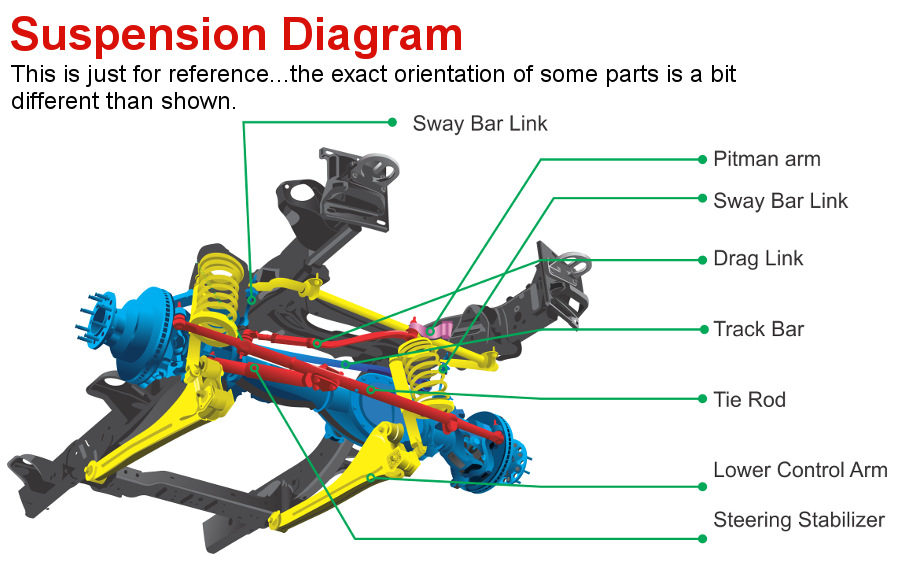
Understanding the front suspension of your Dodge Charger is crucial for performing basic maintenance, diagnosing issues, and even undertaking performance upgrades. This guide delves into the Dodge Charger's front suspension diagram, providing you with the knowledge needed to confidently tackle repairs and modifications. Knowing how the system functions empowers you to better understand your car's handling and responsiveness.
Purpose of the Front Suspension Diagram
A front suspension diagram is more than just a picture; it's a roadmap to understanding the intricate network of components that work together to provide a smooth and controlled ride. It serves several key purposes:
- Repair and Maintenance: The diagram allows you to identify specific parts that need replacement or repair. Instead of blindly guessing, you can pinpoint the exact component causing the problem.
- Troubleshooting: By visually tracing the connections between components, you can diagnose issues such as unusual noises, vibrations, or handling problems.
- Modification and Upgrades: If you're planning to upgrade your suspension with aftermarket parts (e.g., lowering springs, performance shocks), the diagram helps you understand the existing configuration and how the new parts will integrate.
- Learning and Understanding: Even if you're not actively working on your car, studying the diagram provides valuable insight into the workings of your vehicle, enhancing your overall automotive knowledge.
Key Specs and Main Parts of the Dodge Charger Front Suspension
The Dodge Charger typically utilizes an independent front suspension system, often a variation of a short-and-long arm (SLA), or double-wishbone design. While specific details may vary slightly between model years and trim levels, the fundamental components remain consistent. Let's break down the key elements:
- Upper and Lower Control Arms: These are the primary links connecting the wheel hub to the vehicle's frame. They allow the wheel to move up and down while maintaining proper alignment. The upper control arm is typically shorter than the lower control arm, a key characteristic of an SLA suspension.
- Steering Knuckle/Upright: This component houses the wheel hub and bearings and connects to the control arms and steering linkage. It's the pivot point for steering.
- Shock Absorber (Damper): These control the spring's oscillations, preventing the car from bouncing excessively. They work by converting kinetic energy into heat, which is then dissipated.
- Coil Spring: The spring supports the vehicle's weight and absorbs bumps in the road. It provides the initial cushion against impacts. In many Charger models, the coil spring is mounted concentrically around the shock absorber, forming a coilover assembly.
- Sway Bar (Anti-Roll Bar): This torsion bar connects the left and right sides of the suspension. It helps to reduce body roll during cornering by transferring force from one side of the suspension to the other.
- Tie Rods (Inner and Outer): These connect the steering rack to the steering knuckles, translating the driver's steering input into wheel movement.
- Ball Joints: These spherical bearings allow the control arms to move freely while maintaining a secure connection to the steering knuckle. They are critical for smooth suspension articulation and steering.
- Bushings: These rubber or polyurethane components are installed at the pivot points of the suspension (e.g., where the control arms attach to the frame). They absorb vibrations and allow for controlled movement, reducing noise, vibration, and harshness (NVH).
Key Specs often included in suspension diagrams (and sometimes printed on the components themselves) are spring rates (measured in lbs/inch or N/mm), shock absorber damping characteristics (often given as a force curve), and control arm lengths. These specs are essential for selecting compatible replacement or upgrade parts.
Symbols and Conventions in a Suspension Diagram
Understanding the symbols used in a suspension diagram is crucial for accurate interpretation. Here's a breakdown of common conventions:
- Solid Lines: Typically represent rigid components such as control arms, steering knuckles, and the frame.
- Dashed Lines: Often indicate hidden components or lines of action (e.g., the axis of rotation of a joint).
- Different Colors: Used to distinguish between different systems or components. For example, steering components might be colored differently from suspension components. Hydraulic lines (if applicable for active suspension systems) might be a specific color.
- Arrows: Indicate the direction of movement or force.
- Circles or Spheres: Often represent ball joints or pivot points.
- Rectangles: May represent bushings or mounting brackets.
- Part Numbers: Each component will usually be labeled with a unique part number for easy identification and ordering.
The diagram will also feature detailed annotations, indicating component names, dimensions, and material specifications. Pay close attention to the legend or key that accompanies the diagram; this will clarify the meaning of specific symbols and colors.
How the Dodge Charger Front Suspension Works
The front suspension's primary function is to isolate the vehicle's body from road irregularities, providing a comfortable and controlled ride. Here's a simplified explanation of how it works:
- Impact Absorption: When a wheel encounters a bump, the tire absorbs some of the initial impact.
- Spring Compression: The impact force is then transferred to the coil spring, causing it to compress. This stores energy, cushioning the impact.
- Damping: The shock absorber (damper) controls the spring's compression and rebound. It prevents the spring from oscillating excessively, ensuring a smooth and stable ride. Without dampers, the car would continue to bounce after hitting a bump.
- Wheel Movement: The control arms allow the wheel to move up and down while maintaining proper alignment. The SLA design (short-long arm) helps to minimize changes in camber angle (the angle of the wheel relative to vertical) as the suspension travels, improving tire contact and handling.
- Steering: When the driver turns the steering wheel, the steering rack translates this input into linear motion, which is then transferred to the steering knuckles via the tie rods, causing the wheels to turn.
- Roll Control: The sway bar helps to reduce body roll during cornering by transferring force from the outside wheel to the inside wheel. This helps to keep the car flatter and more stable in turns.
Real-World Use: Basic Troubleshooting Tips
Here are a few common suspension issues and how the diagram can help you troubleshoot them:
- Clunking Noises: Could indicate worn ball joints, bushings, or tie rod ends. Use the diagram to identify these components and check for play or damage.
- Squeaking Noises: Often caused by dry or worn bushings. The diagram will show the location of all bushings, allowing you to inspect and lubricate or replace them.
- Excessive Bouncing: Suggests worn shock absorbers. The diagram will help you locate and inspect the shocks for leaks or damage.
- Uneven Tire Wear: Could be caused by misaligned suspension components (e.g., bent control arms). The diagram can help you identify these components and check for damage.
- Poor Handling: Can result from a variety of issues, including worn shocks, damaged springs, or loose ball joints. The diagram provides a visual reference for inspecting all suspension components.
Important Note: Always consult a qualified mechanic for any suspension issues you are unsure about. Working on suspension components can be dangerous if done incorrectly.
Safety Considerations
Working on suspension components can be dangerous due to the high forces involved. Here are some crucial safety precautions:
- Use Jack Stands: Never work under a vehicle supported only by a jack. Always use sturdy jack stands placed on designated jacking points.
- Spring Compression: Coil springs store a tremendous amount of energy. Never attempt to disassemble a strut or coilover assembly without using a proper spring compressor. Improper use of a spring compressor can result in serious injury or death.
- Torque Specifications: Always tighten fasteners to the manufacturer's specified torque. Overtightening or undertightening can compromise the integrity of the suspension. Refer to a service manual for the correct torque values.
- Wear Safety Glasses: Protect your eyes from flying debris.
- Disconnect Battery: While not always strictly necessary for basic suspension work, disconnecting the negative battery terminal helps prevent accidental electrical shorts.
- Consider ABS/Traction Control: When working on components connected to wheel speed sensors (often mounted on the steering knuckle), take extra care not to damage them. Faulty sensors can disable ABS and traction control systems.
Specifically, the coil springs and compressed shock absorbers are potentially lethal. Always use the correct tools and procedures when handling these components. If you are not comfortable working with these parts, it's best to leave the job to a professional.
We have a detailed Dodge Charger Front Suspension Diagram file available for download. Please feel free to use it for your reference.