
Dodge Charger Fuel Pump Wiring Diagram
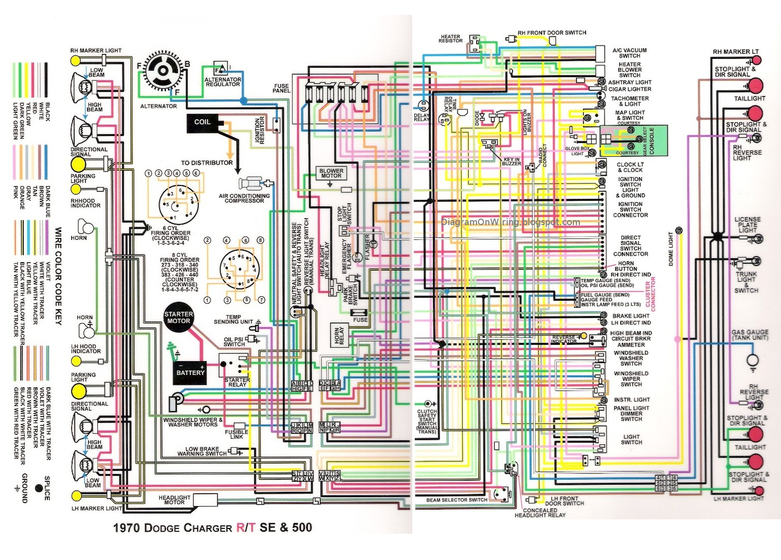
The fuel pump in your Dodge Charger is the heart of its fuel delivery system. Without a functioning fuel pump, your engine simply won't run. Understanding the fuel pump wiring diagram is crucial for diagnosing fuel delivery problems, performing upgrades, or even just gaining a deeper understanding of your car's electrical system. This article will provide a comprehensive overview of the Dodge Charger fuel pump wiring diagram, covering its purpose, key components, how it works, and troubleshooting tips. We'll focus primarily on diagrams from the 2006-2010 (LX Platform) and 2011-2023 (LD Platform) Charger generations, but the underlying principles remain consistent across models.
Purpose of Understanding the Fuel Pump Wiring Diagram
Why bother digging into these diagrams? Here are a few key reasons:
- Troubleshooting Fuel Delivery Issues: A faulty fuel pump, wiring problem, or relay issue can all cause starting problems, poor performance, or even a complete shutdown. The wiring diagram allows you to trace the electrical path and identify the point of failure.
- Performing Fuel Pump Replacements: Replacing the fuel pump often requires disconnecting and reconnecting electrical connectors. Knowing the wiring diagram ensures you reconnect everything correctly, preventing further damage.
- Upgrading Fuel Systems: If you're increasing horsepower with modifications like forced induction (turbo or supercharger), you might need to upgrade your fuel pump. The diagram helps you understand how to properly wire in a larger, aftermarket fuel pump.
- Learning Automotive Electrical Systems: Studying the fuel pump wiring diagram is a great way to learn the basics of automotive electrical circuits, including relays, fuses, and grounding points.
- Adding Custom Features: Want to add a fuel pump kill switch for security? The wiring diagram is essential for safely and effectively interrupting the fuel pump circuit.
Key Specs and Main Parts
Before diving into the specifics, let's define some key components found in most Dodge Charger fuel pump wiring diagrams:
- Fuel Pump: The electric pump itself, usually located inside the fuel tank. It draws fuel from the tank and delivers it to the fuel rail at the engine.
- Fuel Pump Module (FPM): This module (also sometimes called the Fuel Pump Control Module - FPCM) controls the voltage supplied to the fuel pump, thus regulating fuel pressure. Newer Chargers use PWM (Pulse Width Modulation) to control pump speed.
- Fuel Pump Relay: An electrically operated switch that allows a small current from the ignition switch to control a larger current to the fuel pump. It's usually located in the Power Distribution Center (PDC), also known as the fuse box.
- Fuel Pump Fuse: A protective device that prevents excessive current from damaging the fuel pump or wiring. It's also located in the PDC.
- Inertia Switch (Fuel Shut-Off Switch): A safety device that cuts power to the fuel pump in the event of a collision. Not all Chargers have this, but it's worth knowing about.
- Crankshaft Position Sensor (CKP): The ECU uses the CKP signal to determine engine speed and position. The ECU often will not activate the fuel pump if it doesn't get a CKP signal.
- Engine Control Unit (ECU): The "brain" of the engine. It receives signals from various sensors and controls the fuel pump through the fuel pump relay or module.
- Ground (GND): A connection to the vehicle's chassis, providing a return path for the electrical current. A good ground connection is crucial for proper fuel pump operation.
- Battery (B+): The source of electrical power for the fuel pump and other components.
Symbols – Understanding the Diagram's Language
Wiring diagrams use a standard set of symbols to represent electrical components and connections. Here's a brief guide:
- Solid Lines: Represent wires. The thickness of the line doesn't usually indicate wire gauge, but the diagram might specify wire gauge separately.
- Dashed Lines: Often represent signal wires or control circuits with lower current.
- Colors: Wires are identified by their color. Common colors include:
- BK: Black (Usually Ground)
- RD: Red (Usually Battery Positive)
- WT: White
- GN: Green
- BL: Blue
- YL: Yellow
- OR: Orange
- BR: Brown
- Circles: Can represent electrical connectors or splices.
- Squares/Rectangles: Usually represent components like relays, fuses, modules, or switches.
- Resistor Symbol (Zigzag Line): Represents a resistor.
- Diode Symbol (Triangle with a Line): Represents a diode, which allows current to flow in only one direction.
- Ground Symbol (Downward Facing Triangle): Represents a connection to ground.
How It Works – Tracing the Electrical Path
Let's walk through the basic operation of the fuel pump circuit:
- Ignition On: When you turn the ignition switch to the "ON" position, the ECU receives power.
- ECU Activation: The ECU checks for various conditions, such as a signal from the crankshaft position sensor indicating that the engine is cranking or running.
- Relay Activation (Older Models): If the conditions are met, the ECU energizes the fuel pump relay. This sends a small current through the relay's coil, closing the switch inside the relay.
- Power to the Pump: Closing the fuel pump relay allows a larger current from the battery (B+) to flow through the fuel pump fuse and then to the fuel pump.
- Pump Operation: The fuel pump starts running, drawing fuel from the tank and sending it to the fuel rail.
- Module Control (Newer Models): On newer Chargers, the ECU communicates with the Fuel Pump Module (FPM). The FPM then regulates the voltage and current supplied to the fuel pump, controlling its speed and fuel pressure. This is often done using PWM (Pulse Width Modulation).
- Feedback: Some systems have a fuel pressure sensor that provides feedback to the ECU, allowing it to adjust the fuel pump speed for optimal fuel delivery.
Real-World Use – Basic Troubleshooting Tips
Here are some common fuel pump-related issues and how to diagnose them using the wiring diagram and basic tools:
- No Fuel Pump Operation:
- Check the fuel pump fuse. Replace it if it's blown.
- Listen for the fuel pump relay to click when you turn the ignition on. If it doesn't click, try swapping it with a known good relay.
- Use a multimeter to check for voltage at the fuel pump connector when the ignition is on. If there's no voltage, trace the wiring back to the relay or fuse, looking for breaks or shorts.
- Check the ground connection for the fuel pump. A poor ground can prevent the pump from working properly.
- If you have access to a scan tool, check for fuel pump-related DTCs (Diagnostic Trouble Codes).
- Intermittent Fuel Pump Operation:
- Check the fuel pump relay for loose connections or corrosion.
- Inspect the fuel pump wiring for chafing or damage.
- Consider a failing fuel pump motor, which can sometimes operate intermittently before failing completely.
- Low Fuel Pressure:
- Check the fuel filter for clogs.
- Test the fuel pump's output pressure using a fuel pressure gauge.
- On newer models, suspect a faulty Fuel Pump Module (FPM) or a problem with the PWM signal from the ECU.
Important Note: Always disconnect the battery negative terminal before working on any electrical components to prevent shorts and potential damage.
Safety – Handling Fuel Systems with Care
Working on fuel systems involves inherent risks. Gasoline is highly flammable, and electrical sparks can ignite it. Here are some safety precautions:
- Disconnect the Battery: As mentioned before, disconnect the battery negative terminal before starting any work.
- Work in a Well-Ventilated Area: Work outdoors or in a garage with good ventilation to prevent the buildup of flammable vapors.
- No Smoking or Open Flames: Absolutely no smoking or open flames should be present in the work area.
- Use Proper Tools: Use tools that are designed for automotive work, and avoid using tools that could create sparks.
- Fuel Handling: When disconnecting fuel lines, have a container ready to catch any spilled fuel. Dispose of gasoline properly, according to local regulations.
- Fuel Pump Power: The fuel pump connector itself can be a high current circuit. Exercise extreme caution when testing it with a multimeter. Make sure your meter is set to the correct range and that you don't accidentally short the circuit.
Fuel systems, especially the fuel pump and its control circuitry, can be complex. If you're not comfortable working on them, it's best to consult a qualified mechanic.
We have the fuel pump wiring diagram available for download. This diagram will provide the detailed information you need to understand the fuel pump wiring in your Dodge Charger. Download it now and take your troubleshooting to the next level!