Dodge Charger Wiring Harness Diagram
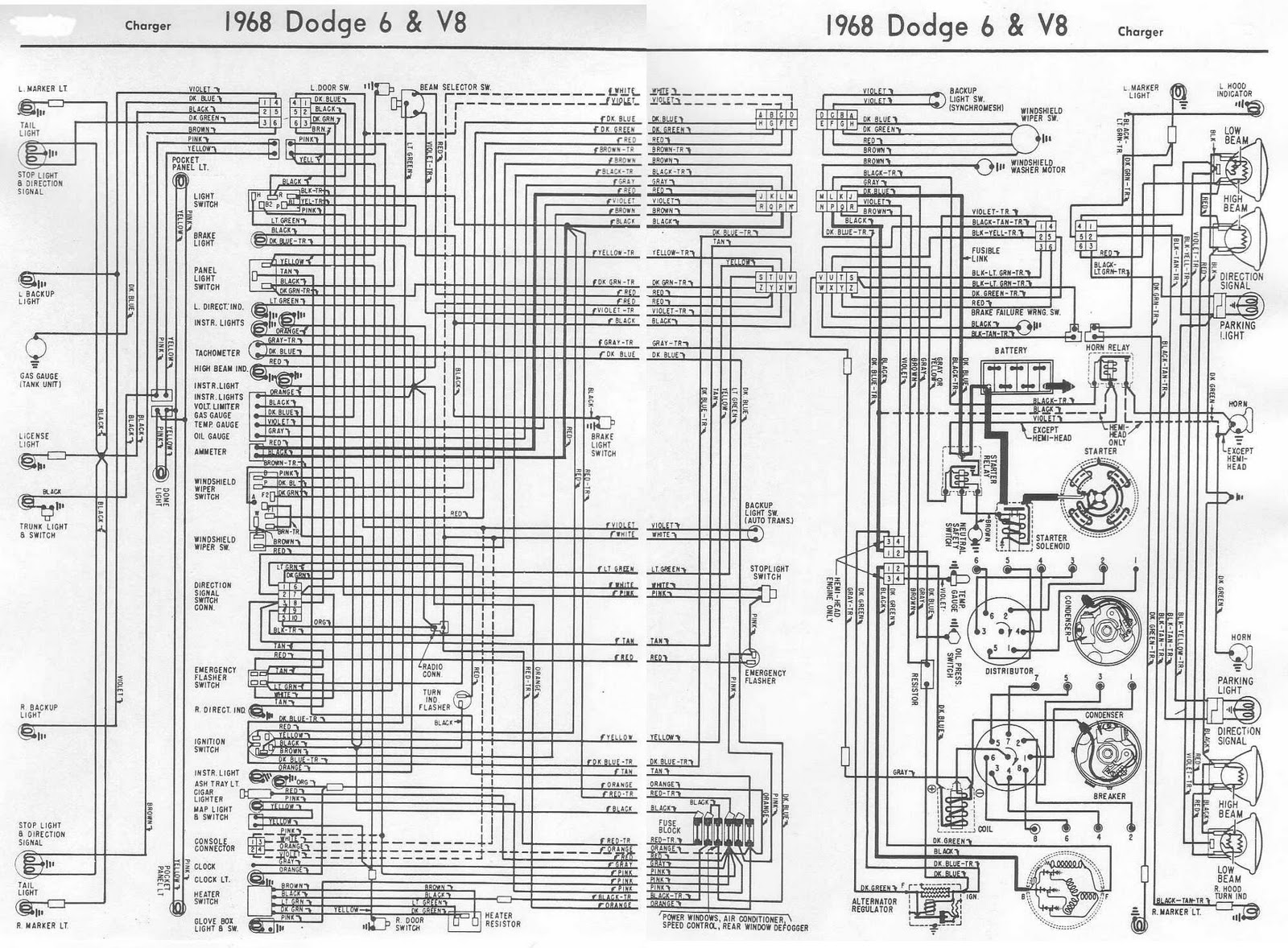
The Dodge Charger, a modern muscle car icon, relies heavily on its intricate network of wiring. Understanding the Charger's wiring harness diagram is crucial for anyone tackling electrical repairs, modifications, or even just wanting to learn more about their vehicle's inner workings. This article will guide you through the fundamentals of the Charger's wiring system, helping you interpret its diagram, understand its operation, and safely perform basic troubleshooting.
Purpose of a Dodge Charger Wiring Harness Diagram
A wiring harness diagram is essentially a roadmap for your car's electrical system. It provides a visual representation of all the wires, connectors, and components, showing how they are interconnected. This is invaluable for:
- Troubleshooting Electrical Problems: Pinpointing the exact location of a short circuit, open circuit, or faulty component.
- Performing Repairs: Replacing damaged wires, connectors, or components correctly.
- Installing Aftermarket Accessories: Safely and effectively connecting new lights, stereos, alarms, or other electrical devices.
- Understanding Vehicle Systems: Gaining a deeper knowledge of how your car's electrical systems function.
- Diagnosing Issues After Modifications: If a modification goes wrong, the diagram helps trace and correct issues.
Without a wiring diagram, electrical work becomes a guessing game, potentially leading to further damage or even dangerous situations.
Key Specs and Main Parts of the Wiring Harness
The Dodge Charger's wiring harness is a complex system comprising numerous sub-harnesses that distribute power and signals throughout the vehicle. Some of the main parts include:
- Engine Harness: Connects the engine's sensors, actuators, and ignition system to the Engine Control Unit (ECU).
- Body Harness: Distributes power and signals to interior components like lights, windows, door locks, and infotainment system.
- Chassis Harness: Connects components related to the vehicle's chassis, such as ABS, suspension sensors, and fuel pump.
- Dashboard Harness: Connects the instrument cluster, switches, and other dashboard components.
Within each harness, you'll find:
- Wires: Conductors made of copper, varying in gauge (thickness) depending on the current they need to carry. Larger gauge numbers indicate thinner wires.
- Connectors: Devices that join wires together, allowing for easy disconnection and reconnection. These come in various shapes and sizes.
- Terminals: Metal contacts inside connectors that make the electrical connection.
- Fuses: Overcurrent protection devices that interrupt the circuit if too much current flows, preventing damage.
- Relays: Electrically operated switches that control high-current circuits using a low-current signal.
- Grounds: Points where circuits are connected to the vehicle's chassis, providing a return path for the current.
Understanding Wiring Diagram Symbols
Wiring diagrams use a standardized set of symbols to represent different components and connections. Here's a breakdown of common symbols:
- Lines: Represent wires. Solid lines indicate a direct connection, while dashed lines may indicate a shielded wire or a connection point on another page of the diagram.
- Colors: Each wire is typically identified by a color code (e.g., BLU for blue, RED for red, GRN for green). This helps trace wires and ensure correct connections.
- Ground Symbol: Often represented by a series of horizontal lines decreasing in length, indicating a connection to the vehicle's chassis ground.
- Battery Symbol: Indicates the vehicle's battery, typically with "+" and "-" symbols to denote polarity.
- Fuse Symbol: A zigzag line within a rectangle. The diagram usually indicates the fuse's amperage rating.
- Relay Symbol: Shows the relay coil and switch contacts. You'll see both normally open (NO) and normally closed (NC) configurations.
- Switch Symbol: Represents various types of switches, such as toggle switches, push-button switches, and multi-position switches.
- Connector Symbol: Typically a circle or square with lines connecting to the wires. The diagram may indicate the connector's part number.
- Component Symbols: Unique symbols represent specific components like lights, motors, sensors, and actuators. Refer to the diagram's legend for details.
Each diagram has a legend or key that explains the specific symbols used within that diagram. Always refer to the legend before attempting to interpret the diagram.
How It Works: Following the Circuit
A wiring diagram essentially allows you to trace the flow of electricity through a circuit. Here's a simplified example:
- Power Source: Electricity originates from the battery (12V).
- Switch: The current flows through a switch. When the switch is closed (turned on), it completes the circuit.
- Component: The current then flows to the component (e.g., a light bulb).
- Ground: After powering the component, the current returns to the battery through a ground connection.
By following the wires and symbols on the diagram, you can trace the path of electricity and identify potential problem areas. Remember to consider the role of fuses and relays in the circuit. A blown fuse indicates an overcurrent condition, while a faulty relay can prevent a component from operating correctly.
Real-World Use: Basic Troubleshooting Tips
Here are some basic troubleshooting tips using a wiring diagram:
- Component Not Working: Check the fuse for that component. If the fuse is blown, replace it with one of the same amperage. If it blows again immediately, there's likely a short circuit. Consult the wiring diagram to trace the circuit and look for damaged wires or components.
- Short Circuit: A short circuit occurs when a wire accidentally touches ground, creating a low-resistance path. The wiring diagram can help you identify potential areas where wires might be chafing or damaged.
- Open Circuit: An open circuit occurs when a wire is broken or disconnected, preventing the flow of electricity. Use a multimeter to test for continuity along the wire. The diagram will show you the wire's path and connection points.
- Voltage Drop: A significant voltage drop along a wire can indicate a corroded connection or a damaged wire. Use a multimeter to measure the voltage at different points along the circuit. The wiring diagram can help you identify the correct test points.
Note: Always disconnect the battery's negative terminal before working on any electrical system to prevent accidental shorts and shocks.
Safety Considerations
Working with automotive electrical systems can be dangerous if proper precautions aren't taken. Always prioritize safety.
- Battery: The battery contains sulfuric acid and can produce explosive gases. Wear safety glasses and gloves when working near the battery.
- Airbag System: The airbag system contains explosive components. Never probe or tamper with airbag wiring unless you are specifically trained and have the proper equipment. Disconnecting the battery is crucial before working near the airbag system. Refer to the service manual for specific deactivation procedures.
- High-Voltage Systems (Hybrid/Electric Vehicles): Some Dodge Charger models may have hybrid or electric variants with high-voltage systems. These systems are extremely dangerous and should only be serviced by qualified technicians.
- Fuses: Never replace a fuse with one of a higher amperage rating. This can overload the circuit and cause a fire.
If you're unsure about any aspect of electrical repair, consult a qualified mechanic.
We have the Dodge Charger Wiring Harness Diagram file available for download. This comprehensive document will be an invaluable resource for your electrical projects. Please note that wiring diagrams can vary depending on the specific model year and trim level of your Charger. Always ensure you're using the correct diagram for your vehicle.