Dodge External Voltage Regulator Wiring Diagram
The external voltage regulator on older Dodge vehicles (typically pre-1970s, but sometimes extending into the early 70s depending on the model) is a key component in the charging system. Unlike modern cars where the voltage regulator is often integrated into the alternator itself or controlled by the engine control unit (ECU), these older Mopars use a separate, electromechanical or solid-state device. Understanding the wiring diagram for this regulator is crucial for troubleshooting charging issues, performing repairs, or even modifying the charging system for performance upgrades. This article will provide a comprehensive breakdown of the Dodge external voltage regulator wiring diagram.
Purpose and Importance
Why bother understanding this diagram? Here are a few key reasons:
- Troubleshooting Charging Problems: Is your battery constantly dying? Is the ammeter showing erratic readings? The external voltage regulator is often the culprit. The wiring diagram provides a roadmap to systematically diagnose faults in the circuit.
- Restoration and Modification: Working on a classic Mopar? A clear understanding of the original wiring is essential for maintaining authenticity or safely modifying the charging system.
- Upgrading to a Modern Alternator: If you're swapping in a more modern, internally regulated alternator, you'll need to know how to bypass or remove the external regulator safely, and the wiring diagram is your guide.
- General Electrical Knowledge: Comprehending this relatively simple circuit helps build a strong foundation for understanding more complex automotive electrical systems.
Key Specs and Main Parts
Before diving into the diagram, let's define some essential components and specifications:
- Voltage Regulator: The heart of the system. Its job is to maintain a stable voltage (typically around 13.8-14.5 volts) to charge the battery and power the car's electrical accessories, regardless of engine RPM.
- Alternator: Generates AC voltage, which is then rectified (converted) to DC voltage to power the car. Older Dodge alternators are often referred to as "field regulated," meaning the regulator controls the current flowing through the alternator's field winding to adjust output.
- Ammeter: (If equipped) Shows the charging or discharging current of the battery. A fluctuating ammeter reading is a common symptom of voltage regulator issues.
- Ignition Switch: Provides power to the voltage regulator when the key is in the "run" position.
- Battery: Stores electrical energy and provides power to start the engine and run accessories when the alternator isn't producing enough power.
- Field Winding: The internal coil inside the alternator. The voltage regulator controls the current flowing through this winding, thereby controlling the output of the alternator.
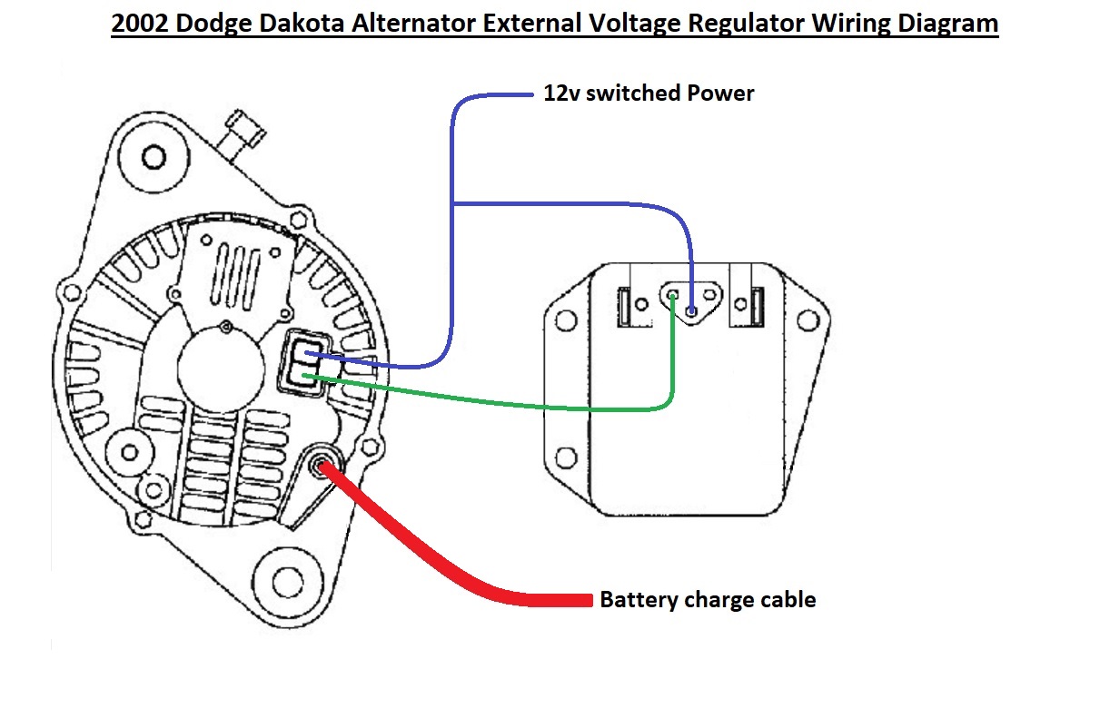
Typical Wiring Colors (Note: These can vary slightly by year and model):
- Dark Blue: Typically the field wire from the voltage regulator to the alternator.
- Green: Usually the ignition switched power to the voltage regulator.
- Black: Ground wire. Essential for proper regulator function.
Understanding Wiring Diagram Symbols
Wiring diagrams use a standardized set of symbols to represent electrical components and connections. Here's a breakdown of common symbols you'll encounter in a Dodge external voltage regulator wiring diagram:
- Solid Lines: Represent wires. Thicker lines often indicate wires carrying higher current.
- Dashed Lines: May indicate wires that are optional or not always present depending on the vehicle configuration.
- Circles: Can represent various components like lamps or connectors, depending on the symbol inside the circle.
- Rectangles: Often represent larger components like the voltage regulator itself.
- Ground Symbol (Typically three lines decreasing in length): Indicates a connection to the vehicle's chassis ground. A good ground connection is crucial for proper operation.
- Connectors: Shown as interlocking shapes, indicating where wires can be disconnected.
- Numbers/Letters: These indicate the gauge (thickness) of the wire and its circuit designation. Refer to your specific wiring diagram key for complete identification.
How It Works: The Charging System in Action
Here's a simplified explanation of how the external voltage regulator system functions:
- When the ignition switch is turned to the "run" position, power is supplied to the voltage regulator (typically through the green wire).
- The voltage regulator monitors the system voltage.
- If the voltage is below the desired level (e.g., when the engine is first started and the battery is depleted), the regulator allows more current to flow through the alternator's field winding (through the dark blue wire).
- Increased current in the field winding strengthens the alternator's magnetic field, causing it to generate more voltage.
- As the system voltage rises, the regulator gradually reduces the current flowing through the field winding, preventing overcharging.
- This constant monitoring and adjustment ensures a stable charging voltage, protecting the battery and electrical components.
- The regulator achieves this using electromechanical points (in older regulators) or solid-state electronics (in later versions).
In essence, the voltage regulator acts like a faucet, controlling the flow of current to the alternator's field winding to maintain a constant voltage output.
Real-World Use: Basic Troubleshooting Tips
Using the wiring diagram, here are some troubleshooting steps for common issues:
- No Charging (Battery Drains Quickly): Use a multimeter to check for voltage at the voltage regulator's power wire (green wire with ignition on). If no voltage, check the wiring from the ignition switch and any fuses in between.
- Overcharging (Battery Boiling): A common cause is a faulty voltage regulator. Use a multimeter to measure the charging voltage at the battery. If it exceeds 14.5 volts, the regulator is likely bad. Also, check the ground connection (black wire) to the voltage regulator. A poor ground can cause erratic operation.
- Erratic Ammeter Readings: This can be caused by a loose or corroded connection in the charging circuit. Inspect all connections, including those at the alternator, voltage regulator, battery, and ammeter. Use the wiring diagram to trace the entire circuit.
- Testing the Regulator: While specific testing procedures vary depending on the regulator type, a basic test involves measuring the voltage at the field wire (dark blue wire) with the engine running. The voltage should fluctuate as the regulator attempts to maintain a stable charging voltage. Consult a repair manual for detailed testing instructions.
Always disconnect the battery's negative terminal before working on the electrical system to prevent accidental shorts.
Safety Considerations
Working with automotive electrical systems can be hazardous. Here are some important safety precautions:
- Battery: Batteries contain sulfuric acid, which can cause burns. Avoid contact with skin and eyes. Hydrogen gas, produced during charging, is explosive. Keep sparks and flames away from the battery.
- Voltage Regulator: Some older voltage regulators contain capacitors that can store a charge even after the battery is disconnected. Discharge these capacitors before handling the regulator.
- Wiring: Never cut or splice wires without disconnecting the battery first. Always use properly sized wire and connectors for repairs.
- Short Circuits: A short circuit can cause wires to overheat and potentially start a fire. Use caution when working around electrical components and ensure that all wiring is properly insulated.
Remember that the external voltage regulator is a relatively simple component, but its proper function is critical to the overall health of your vehicle's electrical system. By understanding the wiring diagram and following safe practices, you can confidently diagnose and repair charging system issues on your classic Mopar.
Disclaimer: Automotive electrical systems can be complex. If you are not comfortable working on electrical systems, consult a qualified mechanic. The information provided here is for educational purposes only and should not be considered a substitute for professional advice.
We have a detailed wiring diagram available for download. This diagram provides a clear visual representation of the connections and components involved. Having this resource readily available will greatly assist you in your troubleshooting and repair efforts. Understanding the wiring will save you time and allow you to proceed confidently with your project. Download and save to reference whenever you need it!