
Dodge Ram 1500 Ignition Coil Diagram
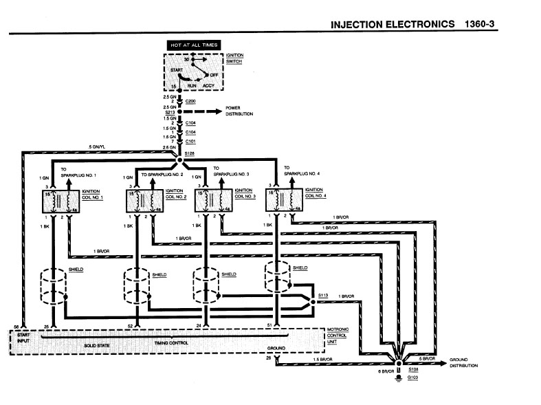
For the seasoned DIYer or aspiring mechanic tackling ignition system issues on a Dodge Ram 1500, understanding the ignition coil diagram is absolutely critical. It's the roadmap that guides you through diagnosing misfires, replacing faulty components, and even potentially upgrading your ignition system for improved performance. This article will break down the diagram, its key components, and how to use it effectively for real-world troubleshooting.
Purpose of the Ignition Coil Diagram
The ignition coil diagram serves several essential purposes:
- Diagnosis: It allows you to trace the electrical circuits that power the ignition coils, helping you pinpoint the root cause of problems like misfires, hard starts, and poor fuel economy. By understanding the diagram, you can systematically check for voltage drops, open circuits, and short circuits.
- Repair: The diagram provides the necessary information to safely and correctly replace faulty ignition coils, wiring harnesses, and related components. Knowing the correct wiring configuration ensures that you don't inadvertently damage other parts of the electrical system.
- Modification & Upgrades: If you're considering upgrading your ignition system for increased spark energy and improved performance (especially common in modified engines), the diagram is crucial for understanding the existing system and integrating aftermarket components.
- Learning: Even if you're not currently facing a specific problem, studying the diagram helps you understand the fundamentals of how the ignition system works, making you a more knowledgeable and capable car owner.
Key Specs and Main Parts
Before diving into the diagram itself, let's review the key specs and main parts of a typical Dodge Ram 1500 ignition system. Keep in mind that specifics may vary slightly depending on the year and engine configuration (3.7L V6, 4.7L V8, 5.7L Hemi, etc.).
- Ignition Coils: These are responsible for stepping up the relatively low voltage from the battery (around 12 volts) to the high voltage (tens of thousands of volts) needed to create a spark at the spark plugs. Many Ram 1500s use a coil-on-plug (COP) design, where each spark plug has its own dedicated ignition coil.
- Ignition Control Module (ICM) or Powertrain Control Module (PCM): The PCM is a central computer that controls many engine functions, including ignition timing and dwell. In some older Rams, a separate ICM might handle ignition control. The PCM or ICM receives signals from various sensors (crankshaft position sensor, camshaft position sensor) and uses this information to trigger the ignition coils at the correct time.
- Crankshaft Position Sensor (CKP): This sensor monitors the position of the crankshaft, providing crucial information to the PCM/ICM about engine speed and crankshaft angle. This information is essential for precise ignition timing.
- Camshaft Position Sensor (CMP): This sensor monitors the position of the camshaft, helping the PCM/ICM determine which cylinder is in the firing position.
- Wiring Harness: The wiring harness connects all the ignition system components, providing pathways for electrical signals and power.
- Spark Plugs: These devices are located in the cylinder head and provide the gap where the high-voltage spark ignites the air-fuel mixture.
- Battery: Provides the initial voltage to power the ignition system.
Understanding the Symbols on the Diagram
Interpreting an ignition coil diagram requires understanding the symbols used to represent different components and connections. Here's a breakdown of common symbols:
- Solid Lines: Represent wires. The thickness of the line doesn't always indicate wire gauge, but it's generally consistent within a single diagram.
- Dashed Lines: Often indicate shielded wires or control signals.
- Circles: Represent connections or splices where multiple wires join.
- Rectangles: Typically represent components like the ignition coil, PCM/ICM, or sensors. The specific function of the rectangle is usually labeled inside or nearby.
- Ground Symbol: A series of decreasing horizontal lines, representing a connection to the vehicle's chassis ground.
- Voltage Source Symbol: A symbol, often a circle with a "+" sign inside, indicating a connection to the battery or a voltage source.
- Resistors: Shown as a zig-zag line.
- Capacitors: Represented by two parallel lines.
- Relays: Shown as a coil and a switch contact.
Color Coding: Wire colors are almost always indicated on the diagram. These colors are crucial for identifying and tracing specific wires in the vehicle. Common abbreviations include:
- BK: Black
- RD: Red
- BL: Blue
- GN: Green
- YL: Yellow
- WT: White
- OR: Orange
For example, a wire labeled "RD/BK" would be a red wire with a black stripe.
How It Works: A Simplified Overview
Here's a simplified explanation of how the ignition system functions:
- The battery provides power to the PCM/ICM and the ignition coils.
- The crankshaft position sensor (CKP) and camshaft position sensor (CMP) send signals to the PCM/ICM, providing information about engine speed and crankshaft/camshaft position.
- The PCM/ICM uses this information to calculate the precise timing for each spark plug.
- The PCM/ICM sends a signal to each ignition coil, triggering it to generate a high-voltage spark. The dwell time (the amount of time the coil is charged before firing) is carefully controlled by the PCM/ICM.
- The high-voltage spark jumps across the spark plug gap, igniting the air-fuel mixture in the cylinder.
Real-World Use: Basic Troubleshooting Tips
Here are some basic troubleshooting tips using the ignition coil diagram:
- Misfire on a Specific Cylinder: If you have a misfire on a specific cylinder, use the diagram to identify the wiring and connections for that cylinder's ignition coil. Check for loose connections, damaged wires, or corrosion. Use a multimeter to check for voltage at the coil connector.
- No Spark at All Cylinders: If you have no spark at all, the problem is likely with a component that affects the entire ignition system, such as the CKP sensor, PCM/ICM, or the main power supply to the ignition coils. Use the diagram to trace the power supply and signal circuits for these components.
- Random Misfires: Random misfires can be caused by a variety of factors, including faulty spark plugs, vacuum leaks, or problems with the PCM/ICM. The diagram can help you check the wiring and connections to the sensors that provide input to the PCM/ICM.
- Using a Multimeter: Refer to the diagram to find the correct pins for testing voltage, continuity, and resistance. Make sure to disconnect the battery before testing resistance to avoid damaging the multimeter or the vehicle's electrical system.
Safety Considerations
Working with the ignition system involves high voltages and potentially dangerous components. Always take the following precautions:
- Disconnect the Battery: Always disconnect the negative battery cable before working on the ignition system. This will prevent accidental shocks and damage to electrical components.
- High Voltage: The ignition coils generate tens of thousands of volts. Never touch the spark plug wires or ignition coils while the engine is running or the ignition is switched on.
- Fuel Hazards: Be careful when working near fuel lines and injectors. Fuel is flammable and can be dangerous if mishandled.
- Consult a Professional: If you are not comfortable working with electrical systems, consult a qualified mechanic.
Important Note: The ignition system is a complex and sensitive part of the vehicle. Incorrect diagnosis or repair can lead to further damage. If you're unsure about any aspect of the troubleshooting process, it's always best to seek professional assistance. Remember to always consult your vehicle's specific repair manual for detailed instructions and torque specifications.
We have a downloadable version of the Dodge Ram 1500 ignition coil diagram available for your convenience. This detailed diagram will provide you with a comprehensive visual representation of the ignition system, making troubleshooting and repairs easier and more accurate.