Dodge Ram Factory Tail Light Wiring Color Code
Understanding the factory tail light wiring color code for your Dodge Ram is crucial for a variety of reasons. Whether you're tackling a repair after a fender bender, upgrading to aftermarket LED tail lights, troubleshooting electrical issues, or simply expanding your automotive knowledge, having a clear grasp of the wiring schematic is invaluable. This article provides a detailed breakdown of the typical Dodge Ram tail light wiring, equipping you with the information needed to confidently work on your vehicle's lighting system.
Why Understanding the Tail Light Wiring Matters
The purpose of this information is multifaceted. Without a clear understanding of the wiring, you risk creating short circuits, damaging the vehicle's electrical system (including the Body Control Module – BCM), or causing malfunctions that could lead to safety hazards on the road. Here's a breakdown of why it's so important:
- Repairs: Identifying the correct wires is critical for repairing damaged wiring due to accidents, corrosion, or rodent damage.
- Upgrades & Modifications: Installing aftermarket tail lights, adding trailer wiring harnesses, or integrating custom lighting solutions requires precise knowledge of the factory wiring.
- Troubleshooting: Diagnosing and resolving lighting problems, such as a malfunctioning brake light or turn signal, becomes much easier with a solid understanding of the wiring diagram.
- Preventing Electrical Damage: Incorrect wiring can lead to short circuits, blown fuses, and potentially damage sensitive electronic components like the BCM.
- Ensuring Safety: Properly functioning tail lights are essential for road safety. Understanding the wiring allows you to ensure that your lights are working correctly.
Key Specs and Main Parts
Before diving into the color codes, let's identify the key components of the Dodge Ram tail light system:
- Tail Light Assembly: The physical housing containing the various lights.
- Brake Light: Illuminates when the brake pedal is pressed, signaling deceleration.
- Turn Signal: Flashes to indicate an intended turn or lane change.
- Tail Light (Running Light): Provides illumination during nighttime driving.
- Reverse Light: Illuminates when the vehicle is in reverse.
- Wiring Harness: A bundle of wires connecting the tail light assembly to the vehicle's electrical system.
- Connectors: Plugs that allow the wiring harness to be easily connected and disconnected from the tail light assembly and the vehicle's wiring.
- Fuses: Safety devices that protect the electrical circuits from overcurrent.
- Body Control Module (BCM): The electronic control unit that manages various vehicle functions, including lighting.
Typical Wiring Colors (Dodge Ram): Keep in mind that wiring colors can sometimes vary slightly depending on the specific year, model, and trim level of your Ram. Always verify the wiring with a reliable diagram specific to your vehicle. Here's a general guideline:
- Black: Ground (Chassis Ground)
- Brown: Tail Lights (Running Lights)
- Yellow: Left Turn Signal/Brake Light
- Green: Right Turn Signal/Brake Light
- White/Gray: Reverse Lights
Understanding Wiring Diagram Symbols
Wiring diagrams use a standardized set of symbols to represent different components and connections. Here are some common symbols you'll encounter:
- Solid Line: Represents a wire. The color of the wire is typically indicated next to the line.
- Dashed Line: Often represents a wire that is part of a harness or a wire that is grounded.
- Circle: Can represent a light bulb, a connector, or other components.
- Ground Symbol: Represents a connection to the vehicle's chassis, providing a return path for the electrical current. The symbol looks like an inverted pyramid or a series of lines decreasing in length.
- Fuse Symbol: Represented by a squiggly line inside a rectangle.
- Connector Symbol: Shows how wires are joined; usually depicted as interlocking shapes.
- Resistor Symbol: A zig-zag line indicating a resistance to electrical flow.
Diagrams often use abbreviations for wire colors. For example, "BK" for Black, "BR" for Brown, "YL" for Yellow, "GN" for Green, and "WT" for White. Understanding these abbreviations is crucial for correctly interpreting the diagram.
How It Works: The Circuit Flow
The tail light system operates on a simple principle: a closed circuit. Electrical current flows from the battery, through a fuse (for protection), to the switch (activated by the brake pedal, turn signal stalk, or headlight switch), then to the appropriate light bulb, and finally back to the battery through the ground connection. The BCM plays a crucial role in controlling the timing and sequencing of the lights, particularly the turn signals.
When you activate the turn signal, the BCM sends a pulsed signal to the corresponding turn signal bulb, causing it to flash on and off. When you press the brake pedal, the brake light switch closes, completing the circuit and illuminating the brake lights. The tail lights (running lights) are typically powered whenever the headlights are switched on.
Pulse Width Modulation (PWM) is a technique sometimes used to control the brightness of the lights. The BCM rapidly switches the power on and off, varying the duty cycle (the percentage of time the power is on) to adjust the light intensity.
Real-World Use: Basic Troubleshooting Tips
Here are some basic troubleshooting tips for common tail light problems:
- Check the Bulbs: This is the first and easiest step. Inspect the filaments of the bulbs for breaks.
- Check the Fuses: Use a multimeter or test light to verify that the fuses for the tail lights, brake lights, and turn signals are intact. The fuse box location and fuse assignments are usually found in your owner's manual.
- Check the Ground Connection: A poor ground connection can cause all sorts of lighting problems. Inspect the ground wires for corrosion or looseness. Clean and tighten the ground connections as needed.
- Use a Multimeter: Use a multimeter to check for voltage at the light bulb socket. If there's no voltage, trace the wiring back to the source (switch, BCM, or fuse) to identify the break in the circuit.
- Inspect the Wiring Harness: Look for damaged, frayed, or corroded wires in the wiring harness. Repair or replace any damaged wiring.
- Test the BCM: If you suspect a problem with the BCM, you may need to take your vehicle to a qualified mechanic for diagnosis and repair. BCM diagnostics often require specialized tools and software.
Safety Precautions
Working with automotive electrical systems can be dangerous. Always disconnect the negative battery cable before working on any electrical components. This will prevent accidental short circuits and electric shocks.
Never work on the electrical system with the engine running. Be careful when working near airbags and other sensitive electronic components. Consult your vehicle's service manual for specific safety precautions.
When working on wiring, use appropriate tools, such as wire strippers, crimpers, and electrical tape or heat shrink tubing. Properly insulate all connections to prevent short circuits.
Disclaimer: Working on vehicle electrical systems carries inherent risks. If you are not comfortable working with electrical wiring, it is best to consult a qualified mechanic.
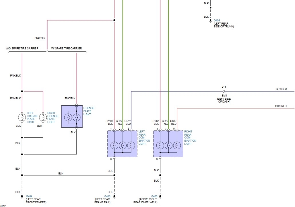
We have a detailed Dodge Ram Factory Tail Light Wiring Diagram available for download. This diagram will provide you with a visual representation of the wiring, making it easier to understand and troubleshoot your vehicle's lighting system. Remember that wiring configurations can vary based on year and trim level, so double-check that the diagram matches your specific vehicle before beginning any work. Download the diagram now to have a valuable resource at your fingertips.