
Double Switch For Fan And Light Wiring
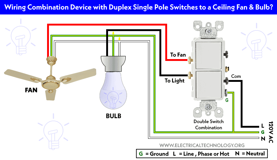
Wiring a ceiling fan and light with separate, independent switches might seem daunting, but it's a project well within reach for the experienced DIYer. This article will break down the wiring diagram step-by-step, explaining the purpose, key components, how it works, and crucial safety considerations. Understanding this wiring configuration is essential for repairs, upgrades, or even designing a new lighting and fan system in your garage or workspace. We'll cover everything you need to know to tackle this project with confidence.
Purpose – Why Understanding This Matters
The ability to independently control a ceiling fan and its light fixture offers both convenience and energy efficiency. You might want the light on without the fan running, or vice versa, depending on the temperature and lighting needs. Understanding the wiring that makes this possible allows you to:
- Troubleshoot existing systems: Diagnose problems like a light that won't turn on or a fan that runs erratically.
- Install new fixtures: Confidently wire a new ceiling fan with independent light control.
- Modify existing systems: Upgrade a single-switch system to a dual-switch setup.
- Improve energy efficiency: Use only the light or fan as needed, reducing energy consumption.
- Gain a deeper understanding of electrical circuits: Expand your electrical DIY skills.
Key Specs and Main Parts
Before diving into the wiring, let's define the key components and their specifications. Keep in mind that local electrical codes may dictate specific requirements, so always consult them before starting any electrical work.
Main Parts:
- Ceiling Fan/Light Fixture: The core component, usually with separate wires for the fan motor and the light. These will likely be labeled in the fan's installation manual.
- Two Single-Pole, Single-Throw (SPST) Switches: These are the standard on/off switches. Each switch controls a single circuit. These are sometimes referred to as toggle switches.
- Electrical Junction Box: The box in the ceiling where the wires from the power source and the fan meet. It must be rated for the weight of the fan.
- Wiring: Typically, Non-Metallic (NM) cable, commonly called Romex, is used. The gauge (e.g., 14 AWG or 12 AWG) depends on the circuit's amperage and local codes.
- Wire Connectors (Wire Nuts): Used to safely join wires together. Use appropriately sized connectors for the number and gauge of wires being connected.
Key Specs:
- Voltage: In most residential applications, this is 120V AC (Alternating Current).
- Amperage: The circuit breaker protecting the circuit will dictate the maximum amperage. Ensure the fan and light combined draw less than this limit.
- Wire Gauge: Use the correct wire gauge based on the amperage. 14 AWG is typically suitable for 15-amp circuits, and 12 AWG for 20-amp circuits.
- Fan and Light Wattage: Know the wattage of the fan motor and the light fixture to calculate the total load on the circuit.
Symbols – Understanding the Wiring Diagram
Wiring diagrams use standard symbols to represent components and connections. Understanding these symbols is crucial for interpreting the diagram and wiring the system correctly.
- Solid Black Line: Represents a wire carrying electrical current.
- White Line (Often with Grey Dashes): Represents the neutral wire.
- Green or Bare Copper Line: Represents the ground wire.
- Circle with an 'X': Typically represents a light fixture.
- Curved Blade Shape: Represents a fan motor.
- SPST Switch Symbol: A line connected to a pivot point that can be opened or closed.
- Wire Nut Symbol (Small Filled Circle): Indicates where wires are joined together.
Color coding is also important. In the US, the standard color codes are:
- Black: Hot wire (carries the electrical current).
- White: Neutral wire (returns the current to the source).
- Green or Bare Copper: Ground wire (provides a safety path for electricity).
How It Works – The Electrical Flow
The basic principle is to route the hot wire from the power source to each switch independently. Each switch then controls the flow of electricity to either the fan motor or the light fixture. The neutral wire provides the return path for the current, and the ground wire provides a safety path in case of a fault.
- Power Source: The hot (black) wire from the breaker panel enters the electrical junction box.
- Hot Wire Split: Inside the junction box, the hot wire is split into two separate hot wires. This is done using wire connectors (wire nuts).
- Switch Connection: Each of these new hot wires is connected to one of the terminals on each SPST switch.
- Load Wires: From the other terminal on each switch, a "load wire" (usually black, but sometimes red) runs to the ceiling fan/light fixture. One load wire goes to the fan motor, and the other goes to the light fixture.
- Neutral Connection: The neutral (white) wire from the power source is connected directly to the neutral wires of both the fan motor and the light fixture inside the junction box.
- Ground Connection: The ground (green or bare copper) wire from the power source is connected to the ground terminals of the junction box, the fan, and the light fixture.
When a switch is turned "on," it closes the circuit, allowing electricity to flow from the hot wire through the switch, through the load wire, and to the corresponding device (fan or light). The electricity then returns through the neutral wire, completing the circuit.
Real-World Use – Basic Troubleshooting Tips
Even with a solid understanding of the wiring diagram, problems can arise. Here are some basic troubleshooting tips:
- No Power: Check the circuit breaker. If it's tripped, reset it. If it trips again immediately, there's likely a short circuit.
- One Function Not Working (Fan or Light): Check the corresponding switch. Test the switch with a multimeter to ensure it's functioning correctly. Also, check the wiring connections to the device that isn't working.
- Dim Light or Slow Fan Speed: Check for loose connections. Loose connections can create resistance, reducing voltage and affecting performance.
- Humming Noise: This could indicate a problem with the fan motor or a loose connection. Tighten all connections and consider lubricating the fan motor.
- Use a Multimeter: A multimeter is your best friend for electrical troubleshooting. Learn how to use it to check voltage, continuity, and resistance. Always disconnect power before working on any electrical circuits!
Safety – Handle With Care
Electricity is dangerous. Always prioritize safety when working with electrical circuits.
- Turn Off the Power: Always turn off the circuit breaker that supplies power to the circuit you're working on before you start. Double-check with a non-contact voltage tester to confirm the power is off.
- Use Proper Tools: Use insulated tools designed for electrical work.
- Wear Safety Gear: Wear safety glasses to protect your eyes.
- Inspect Wiring: Carefully inspect all wiring for damage or wear. Replace any damaged wiring.
- Grounding: Ensure proper grounding. Grounding is a crucial safety feature that protects against electrical shock.
- Overhead power lines: be aware of any overhead power lines when working.
- If Unsure, Hire an Electrician: If you're not comfortable working with electricity, or if you encounter any problems you can't resolve, consult a qualified electrician. It's always better to be safe than sorry. The cost of a professional is far less than the risk of injury or property damage.
Remember, this guide provides a general overview. Always consult local electrical codes and regulations. With careful planning and a focus on safety, you can successfully wire a ceiling fan and light with independent switches.
We have a detailed wiring diagram available for download. It includes clear visuals and step-by-step instructions to guide you through the process. This diagram can be an invaluable resource, especially when tackling this project for the first time.