
Dual Electric Fan Relay Wiring Diagram
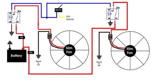
Dual electric fan setups are a popular upgrade for many vehicles. They offer improved cooling over a single mechanical or electric fan, especially in high-performance applications or hot climates. Understanding the wiring behind a dual electric fan relay system is crucial for proper installation, troubleshooting, and maintenance. This article dives deep into the wiring diagram, explaining the purpose, components, operation, and safety considerations involved.
Purpose of a Dual Electric Fan Relay Wiring Diagram
Why bother understanding this diagram? Well, several reasons. First, if you're upgrading your cooling system with dual electric fans, the diagram is your roadmap to a successful installation. It tells you exactly where each wire goes, preventing costly mistakes and potential damage to your electrical system. Second, if your existing dual fan setup malfunctions, the diagram helps you troubleshoot the problem. You can trace the circuit, identify faulty components, and perform targeted repairs. Third, understanding the diagram allows you to customize the system. You might want to add a manual override switch, adjust the fan activation temperatures, or integrate the fans with your vehicle's ECU (Engine Control Unit). Finally, even if you don’t plan to work on your car yourself, understanding the basics allows you to better communicate the problem to your mechanic, potentially saving time and money. In essence, knowledge is power (and less chance of getting ripped off!).
Key Specs and Main Parts
Before we delve into the wiring itself, let's define the key components you'll find in a typical dual electric fan relay system:
- Relays: These are electromechanical switches. A small current in the relay's coil closes a larger circuit, allowing a high current to flow to the fans. We’re usually talking about automotive relays rated for 30-40 amps. These are essential because the fans draw a considerable amount of current, which could damage smaller switches or wiring. Dual fan setups typically use two relays – one for each fan, or one for low-speed and one for high-speed operation (more on that later).
- Fans: The electric fans themselves, rated for a specific voltage (usually 12V in automotive applications) and current draw. The Combined amperage of both fans is crucial for selecting appropriate relay(s) and fuse(s).
- Temperature Sensor (or Thermostat Switch): This component senses the engine coolant temperature and triggers the relays when a specific temperature threshold is reached. These can be in-line sensors mounted in the radiator hose or threaded directly into the engine block or intake manifold. The sensor can be a simple on/off switch or a more sophisticated sensor providing variable resistance to the ECU.
- Fuse(s): A critical safety component. Fuses protect the wiring and components from overcurrent conditions. The fuse rating should be slightly higher than the maximum current draw of the fan(s), but low enough to protect the wiring.
- Wiring: Automotive-grade wiring of appropriate gauge (thickness) is essential. The gauge depends on the current draw and the length of the wire. Using undersized wiring can lead to overheating, voltage drop, and even fire.
- Grounding Points: Solid, clean ground connections are vital for the proper operation of any electrical circuit. Poor grounding can lead to intermittent problems and reduced fan performance.
- Connectors: High-quality connectors are necessary for reliable connections. Crimp-on connectors with heat shrink tubing are a good choice.
Symbols – Deciphering the Diagram
Understanding the symbols used in a wiring diagram is crucial for interpreting it correctly. Here are some common symbols you'll encounter:
- Solid Lines: Represent wires. The thickness of the line *doesn't* necessarily indicate wire gauge, though sometimes diagrams will vary the line thickness for clarity.
- Dashed Lines: Often indicate connections that are optional or may vary depending on the specific application.
- Circles: Can represent various components, such as lights, switches, or sensors. The specific symbol inside the circle provides more detail.
- Rectangles: Commonly represent relays. Inside the rectangle, you'll typically see a coil symbol (a spiral or loop) and switch contacts.
- Ground Symbol: Usually a series of horizontal lines decreasing in length, representing a connection to the vehicle's chassis ground.
- Fuse Symbol: A squiggly line inside a rectangle.
- Colors: Wiring diagrams often use color coding to differentiate wires. Common colors include red (power), black (ground), blue, green, yellow, and white. However, never rely solely on wire color when making connections. Always verify the function of the wire with a multimeter.
Important Note: Always consult the specific wiring diagram for your fan system. General diagrams can provide guidance, but there may be variations.
How It Works – The Circuit in Action
Let's break down how a typical dual electric fan relay system operates. The temperature sensor monitors the engine coolant temperature. When the temperature reaches a predetermined threshold (e.g., 195°F), the sensor closes a circuit, sending a small current to the coil of the primary relay. This energizes the relay coil, which magnetically pulls the relay's contacts closed. This allows a high-current circuit to flow from the battery, through a fuse, to the first electric fan, and then to ground. This causes the first fan to spin up, providing cooling. If the engine temperature continues to rise and reaches a higher threshold (e.g., 210°F), the temperature sensor may close a second circuit, activating a second relay. This second relay then powers the second fan in a similar manner. Some systems utilize a 2-speed fan, with one relay powering the fan at low speed (often through a resistor to reduce voltage and current) and the second relay switching the fan to high speed by bypassing the resistor.
Two-Speed Fan Control Example:
A common setup involves two relays. Relay 1 powers the fan at low speed. This is achieved by sending power through a resistor, reducing the voltage and current, resulting in a slower fan speed and less noise. When the temperature rises further, Relay 2 is energized. Relay 2 bypasses the resistor, providing full voltage to the fan, causing it to operate at high speed. This provides maximum cooling when needed. This type of setup is often controlled by the ECU, which reads the coolant temperature sensor and activates the relays accordingly.
Real-World Use – Basic Troubleshooting Tips
If your dual electric fan system isn't working correctly, here are some basic troubleshooting steps you can take, using the wiring diagram as a guide:
- Check the Fuses: This is the first and easiest step. Use a multimeter to check for continuity across the fuse. If the fuse is blown, replace it with a fuse of the same amperage rating. If the fuse blows repeatedly, there's a short circuit somewhere in the system.
- Test the Relays: You can test a relay by applying 12V to the coil terminals and checking for continuity between the switch terminals. Alternatively, you can swap relays with a known good relay (of the same type) to see if that resolves the problem.
- Check the Temperature Sensor: Use a multimeter to check the resistance of the temperature sensor. The resistance should change as the temperature changes. Consult the sensor's specifications for the correct resistance values at different temperatures.
- Inspect the Wiring: Look for damaged, frayed, or corroded wires. Pay close attention to connections, especially ground connections. Clean and tighten any loose connections.
- Verify Ground Connections: Poor grounding is a common cause of electrical problems. Ensure that all ground connections are clean, tight, and free of corrosion.
- Voltage Drop Testing: Perform voltage drop tests on the power and ground circuits to identify areas of high resistance. Excessive voltage drop indicates a problem with the wiring or connections.
Safety – Handling Electricity with Care
Working with automotive electrical systems can be dangerous if you're not careful. Here are some important safety precautions to keep in mind:
- Disconnect the Battery: Always disconnect the negative battery cable before working on any electrical system. This will prevent accidental short circuits and electrical shocks.
- Work in a Well-Ventilated Area: When soldering or working with chemicals, work in a well-ventilated area to avoid inhaling harmful fumes.
- Use Proper Tools: Use insulated tools designed for automotive electrical work.
- Never Work on a Live Circuit: Unless absolutely necessary for troubleshooting, never work on a live circuit.
- Be extra cautious when working with the battery or the main power wires to the relays. These components can deliver a large amperage and can generate excessive heat. Short circuits here can result in a fire.
- Double-Check Your Work: Before reconnecting the battery, double-check all your connections to ensure they are correct and secure.
This article provides a comprehensive overview of dual electric fan relay wiring diagrams. With this knowledge, you'll be better equipped to install, troubleshoot, and maintain your dual fan system.
We have a printable, high-resolution version of a sample dual electric fan relay wiring diagram available for download. This diagram includes color-coded wiring and detailed component labeling to help you visualize the system. Please click here to download the diagram.