
Ecu Nissan Wiring Diagram Color Codes
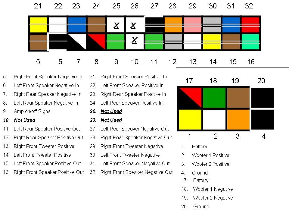
Understanding the ECU (Engine Control Unit) wiring diagram for your Nissan is crucial for a variety of tasks, from diagnosing electrical problems to performing custom modifications. The wiring diagram serves as a roadmap to the vehicle's electrical system, specifically the ECU's connections, allowing you to pinpoint faults, install aftermarket components, and gain a deeper understanding of how your engine operates. We'll explore Nissan ECU wiring diagram color codes in depth, focusing on the specific information the wiring diagrams contain and how to use them effectively.
Purpose of a Nissan ECU Wiring Diagram
The primary purpose of an ECU wiring diagram is to provide a visual representation of the ECU's electrical connections. This documentation is essential for:
- Troubleshooting: Identifying and resolving electrical issues related to sensors, actuators, and the ECU itself.
- Repair: Fixing damaged wiring, replacing faulty components, and restoring the ECU's functionality.
- Modification: Installing aftermarket parts, such as performance chips, gauges, and sensors, by correctly identifying the corresponding ECU pins.
- Education: Learning the intricacies of the engine management system and understanding how different components interact.
Without a reliable wiring diagram, attempting any electrical work on your Nissan's ECU is risky and can lead to further damage. This resource helps to ensure accuracy, safety, and efficiency in your repairs or modifications.
Key Specs and Main Parts of the ECU Wiring Diagram
A typical Nissan ECU wiring diagram will contain several key pieces of information. Here's a breakdown of the essential parts:
- ECU Pinout: This is arguably the most critical section. It lists each pin on the ECU connector and details its function. For example, you might see "Pin 12: Crankshaft Position Sensor Signal."
- Wire Colors: Every wire in the diagram is represented by a specific color code (e.g., "L/W" for Blue with White stripe). Understanding these color codes is paramount.
- Component Symbols: The diagram will use standardized symbols to represent various electrical components like sensors (e.g., Mass Air Flow - MAF, Oxygen sensor), actuators (e.g., fuel injectors, idle air control valve), relays, fuses, and grounds.
- Ground Points: These are points where the electrical system is connected to the vehicle's chassis for grounding. Proper grounding is crucial for the ECU to function correctly.
- Voltage Levels: Some diagrams specify the expected voltage levels at certain pins, which is extremely useful for diagnosing voltage-related problems.
- Connector Views: Diagrams often include diagrams of the ECU connectors themselves, showing the physical arrangement of the pins.
Understanding ECU Wiring Diagram Symbols
ECU wiring diagrams utilize a standardized set of symbols to represent different electrical components and connections. Deciphering these symbols is fundamental to interpreting the diagram correctly. Here's a breakdown of common symbols:
- Lines: Solid lines represent wires, and dashed lines may indicate shielded wiring or connections within a module. The thickness of the line does not generally indicate wire gauge.
- Colors: Wire colors are indicated by abbreviations. For example:
- B: Black
- W: White
- R: Red
- G: Green
- L: Blue
- Y: Yellow
- Br: Brown
- P: Pink
- O: Orange
- Component Symbols: These vary depending on the component. A resistor is usually a zig-zag line. A capacitor is often two parallel lines. A ground is typically represented by a set of decreasing horizontal lines or a triangle pointing downwards. A diode will have a triangle pointing toward a vertical line.
- Connectors: Represented by a block with pins labeled. The diagram will often indicate the connector's name or code (e.g., "E14").
- Splices: A dot where multiple wires connect. Beware of these as they can be corrosion hot spots.
Always refer to the legend or key accompanying the specific wiring diagram you are using, as symbols can vary slightly between manufacturers and even different Nissan models.
How It Works: Tracing a Circuit
Using the wiring diagram effectively involves tracing circuits to understand how different components interact. Let's say you suspect a faulty MAF sensor. Here's how you might use the wiring diagram:
- Locate the MAF Sensor: Find the MAF sensor symbol on the diagram. Note the wires connected to it and their color codes.
- Trace the Wires: Follow each wire connected to the MAF sensor back to the ECU or other components. Pay attention to any splices, connectors, or intermediate components along the way.
- Identify ECU Pins: Determine which ECU pins the MAF sensor signals are connected to. This information is crucial for testing the signals at the ECU.
- Check for Power and Ground: Verify that the MAF sensor is receiving power and ground. The wiring diagram will show you the power and ground connections.
- Test Signal Continuity: Using a multimeter, check the continuity of the wires between the MAF sensor and the ECU. This verifies that the wires are not broken or shorted.
By systematically tracing the circuit, you can isolate the problem area and pinpoint the faulty component or wiring.
Real-World Use: Basic Troubleshooting Tips
Here are some practical troubleshooting tips for using your Nissan ECU wiring diagram:
- Start with the Basics: Before diving into the wiring diagram, check the basics: battery voltage, fuses, and ground connections. A weak battery or a blown fuse can cause a wide range of problems.
- Use a Multimeter: A multimeter is your best friend when troubleshooting electrical problems. Use it to measure voltage, resistance, and continuity.
- Check for Corrosion: Corrosion can cause poor connections and voltage drops. Inspect connectors and wiring harnesses for signs of corrosion, especially in areas exposed to moisture.
- Isolate the Problem: Use the wiring diagram to isolate the problem area. Disconnect connectors to narrow down the source of the fault.
- Verify ECU Power and Ground: Ensure the ECU is receiving proper power and ground. A faulty ground connection can cause all sorts of weird issues.
- Consult Technical Service Bulletins (TSBs): Check for any TSBs related to your vehicle and the specific problem you're experiencing. TSBs often contain valuable troubleshooting information and repair procedures.
Example: Let's say your Nissan is throwing a code for a faulty oxygen sensor (O2 sensor). Using the wiring diagram, you can identify the O2 sensor's wiring, including the heater circuit and signal wire. Check the heater circuit for proper voltage and ground. Then, test the signal wire for proper voltage variations while the engine is running. This will help determine if the O2 sensor itself is faulty or if the problem lies in the wiring harness.
Safety Considerations
Working with automotive electrical systems can be dangerous. Here are some safety precautions to keep in mind:
- Disconnect the Battery: Always disconnect the negative battery terminal before working on the electrical system. This prevents accidental shorts and potential electrocution.
- Be Aware of High-Voltage Components: The ignition system and the fuel injection system involve high-voltage components. Use extreme caution when working near these systems. Never probe the primary ignition circuit without appropriate training and equipment.
- Use Insulated Tools: Use insulated tools to prevent accidental shorts.
- Work in a Well-Ventilated Area: When working with fuel or other flammable liquids, work in a well-ventilated area to prevent the build-up of explosive fumes.
- Consult the Service Manual: Always refer to the service manual for your vehicle for specific safety precautions and repair procedures.
Remember, electricity can be dangerous. If you are not comfortable working with electrical systems, consult a qualified mechanic.
We have the complete wiring diagram file ready for you to download. This comprehensive resource will provide detailed information about your Nissan's ECU wiring system.