
Electric Brake Controller Wiring Diagram
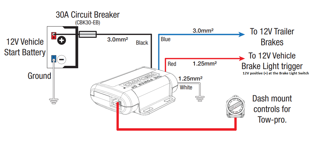
So, you're diving into the world of electric brake controllers, huh? Good on you! They're essential for safely towing heavier trailers, especially those with electric brakes. Understanding the wiring is crucial, whether you're troubleshooting a faulty system, installing a new controller, or just want to understand how it all works. This article will walk you through a typical electric brake controller wiring diagram, explaining the components and connections in plain English.
Why Bother Understanding the Wiring Diagram?
Let's face it, electrical problems can be a real pain. A solid understanding of the wiring diagram is invaluable for several reasons:
- Troubleshooting: When your trailer brakes aren't working properly, the diagram is your roadmap. It helps you trace the circuit, identify potential faults (like shorts or open circuits), and pinpoint the problematic component.
- Installation: Installing a new electric brake controller can be a DIY project, but only if you know what you're doing. The diagram ensures you connect everything correctly, avoiding potentially dangerous wiring errors.
- Modification: Maybe you want to add a manual override switch or incorporate additional features. The diagram shows you where to tap into the circuit without damaging anything.
- General Understanding: Simply knowing how the system operates gives you more confidence and allows you to communicate effectively with a mechanic if you need professional help.
Key Specs and Main Parts of an Electric Brake Controller System
Before we jump into the diagram itself, let's define some key components and their specifications. These components are crucial to understand, and their specifications can vary based on the trailer and vehicle.
- Electric Brake Controller: The brains of the operation. It senses the vehicle's deceleration and applies a proportional voltage to the trailer brakes. Specs to consider include output amperage (typically 10-15 amps for dual-axle trailers) and brake type compatibility (proportional or time-delayed).
- 7-Way Connector (Trailer Side): This is the standard connector that bridges the electrical connection between your tow vehicle and the trailer. Important pins include:
- Ground (White)
- Taillights (Brown)
- Left Turn/Brake (Yellow)
- Right Turn/Brake (Green)
- Auxiliary 12V+ Power (Black) – Used for charging trailer batteries or powering accessories.
- Reverse Lights (Blue or Purple)
- Brake Output (Blue) – This is the critical wire for the electric brakes.
- 7-Way Connector (Vehicle Side): The mating connector on your tow vehicle that accepts the trailer's 7-way connector. The pinout must match the trailer's connector.
- Brake Magnets: Located inside the brake drums of the trailer, these magnets are energized by the brake controller's output. They attract to the brake drum and engage the brake shoes. The amperage draw of each magnet is important; a typical magnet might draw 3 amps. This affects the overall controller amperage requirement.
- Wiring: The gauge (thickness) of the wiring is critical. Generally, 12-gauge wire is sufficient for most electric brake applications, but heavier trailers might require 10-gauge wire, especially for the 12V+ auxiliary power and brake output wires. Using too small of a gauge wire can cause voltage drop and overheating.
- Fuses and Circuit Breakers: These protect the electrical system from overloads. A dedicated fuse (usually 20-30 amps) should be installed in the vehicle's fuse box for the brake controller power supply. The controller itself might also have an internal fuse.
- Ground Connections: A solid ground is absolutely critical. Poor grounding is a major source of electrical problems. Ensure all ground connections are clean, tight, and free of corrosion.
Understanding Wiring Diagram Symbols
Wiring diagrams use standardized symbols to represent components and connections. Here's a breakdown of common symbols you'll encounter:
- Solid Lines: Represent wires. The thickness may indicate wire gauge.
- Dashed Lines: Often indicate optional connections or wires that are part of a harness but may not be used in all applications.
- Circles with Numbers: Usually indicate the pin numbers on a connector.
- Ground Symbol (Three Horizontal Lines Descending): Indicates a connection to ground (the vehicle chassis).
- Fuse Symbol (S-shaped line): Represents a fuse. The diagram should indicate the fuse amperage.
- Switch Symbol (Line Connecting to Two Terminals): Represents a switch. The diagram may show the switch positions (e.g., ON/OFF).
- Connector Symbol (Interlocking Shapes): Represents a connector where wires can be joined or separated.
Color Coding: Wire colors are also standardized, although slight variations can occur between manufacturers. Common colors include:
- Red: Usually indicates a positive (+) power supply.
- Black: Usually indicates ground (-).
- Blue: Almost always the brake controller output wire to the trailer brakes.
- White: Typically used for ground connections.
- Brown, Yellow, Green: Generally used for lighting circuits (taillights, turn signals, brake lights).
How It Works: A Simplified Circuit
Let's break down how the electric brake controller system actually works:
- The brake controller receives power from the vehicle's battery, typically through a dedicated fuse in the fuse box.
- The controller monitors the vehicle's deceleration using an internal accelerometer (for proportional controllers) or a timer (for time-delayed controllers).
- When the vehicle's brakes are applied, the controller sends a proportional amount of voltage to the blue brake output wire.
- The blue wire connects to the 7-way connector and then to the trailer's wiring harness.
- The blue wire then distributes power to the brake magnets inside each of the trailer's brake drums.
- The energized magnets attract to the rotating brake drum, forcing the brake shoes against the drum and applying the brakes.
- The amount of braking force applied to the trailer is directly proportional to the voltage sent by the brake controller, ensuring smooth and coordinated braking.
- A solid ground connection is crucial for the entire circuit to function correctly.
Real-World Use: Basic Troubleshooting Tips
Having trailer brake issues? Here are some basic troubleshooting tips:
- No Trailer Brakes:
- Check the fuse for the brake controller. Replace if blown.
- Inspect the 7-way connector for corrosion or damaged pins. Clean or replace as needed.
- Use a multimeter to check for voltage at the blue wire on the trailer side of the 7-way connector when the brake pedal is depressed. If there's no voltage, the problem is likely in the vehicle's wiring or the brake controller itself.
- Check the ground connections. A bad ground can cause all sorts of problems.
- If you suspect the brake controller, try testing it with a known good trailer (if available) or having it professionally tested.
- Weak Trailer Brakes:
- Adjust the brake controller gain. This controls the amount of voltage sent to the trailer brakes.
- Check the brake magnets for wear. Over time, they can lose their effectiveness.
- Inspect the brake shoes for wear or contamination.
- Ensure the trailer brakes are properly adjusted.
- Trailer Brakes Locking Up:
- Reduce the brake controller gain.
- Check for a short circuit in the trailer wiring.
Safety: Proceed with Caution!
Working with electrical systems can be dangerous. Here are some important safety precautions:
- Disconnect the Negative Battery Terminal: Always disconnect the negative (-) battery terminal before working on any electrical wiring. This prevents accidental short circuits and electrical shocks.
- Use a Multimeter: A multimeter is your best friend for diagnosing electrical problems. Learn how to use it to check for voltage, continuity, and resistance.
- Work in a Well-Lit Area: Good visibility is essential for safety and accuracy.
- Protect Your Eyes: Wear safety glasses to protect your eyes from sparks or debris.
- Be Aware of Hot Wires: Even with the battery disconnected, capacitors can store energy. Discharge them carefully before working on sensitive components.
- Consult a Professional: If you're uncomfortable working with electrical systems, don't hesitate to consult a qualified mechanic. Improper wiring can be dangerous and could damage your vehicle or trailer. Especially if you're dealing with high-amperage circuits – these can generate a lot of heat and cause fires if not wired correctly.
Remember, safety first! Take your time, double-check your work, and don't be afraid to ask for help if you need it.
You've now got a solid understanding of electric brake controller wiring diagrams. It's a complex system, but with a little knowledge and care, you can troubleshoot problems, install new components, and keep your trailer brakes working safely and reliably.
And remember, we have a sample electric brake controller wiring diagram file available for download. Feel free to use it as a reference during your next project.