
Electric Brake Trailer Wiring Diagram
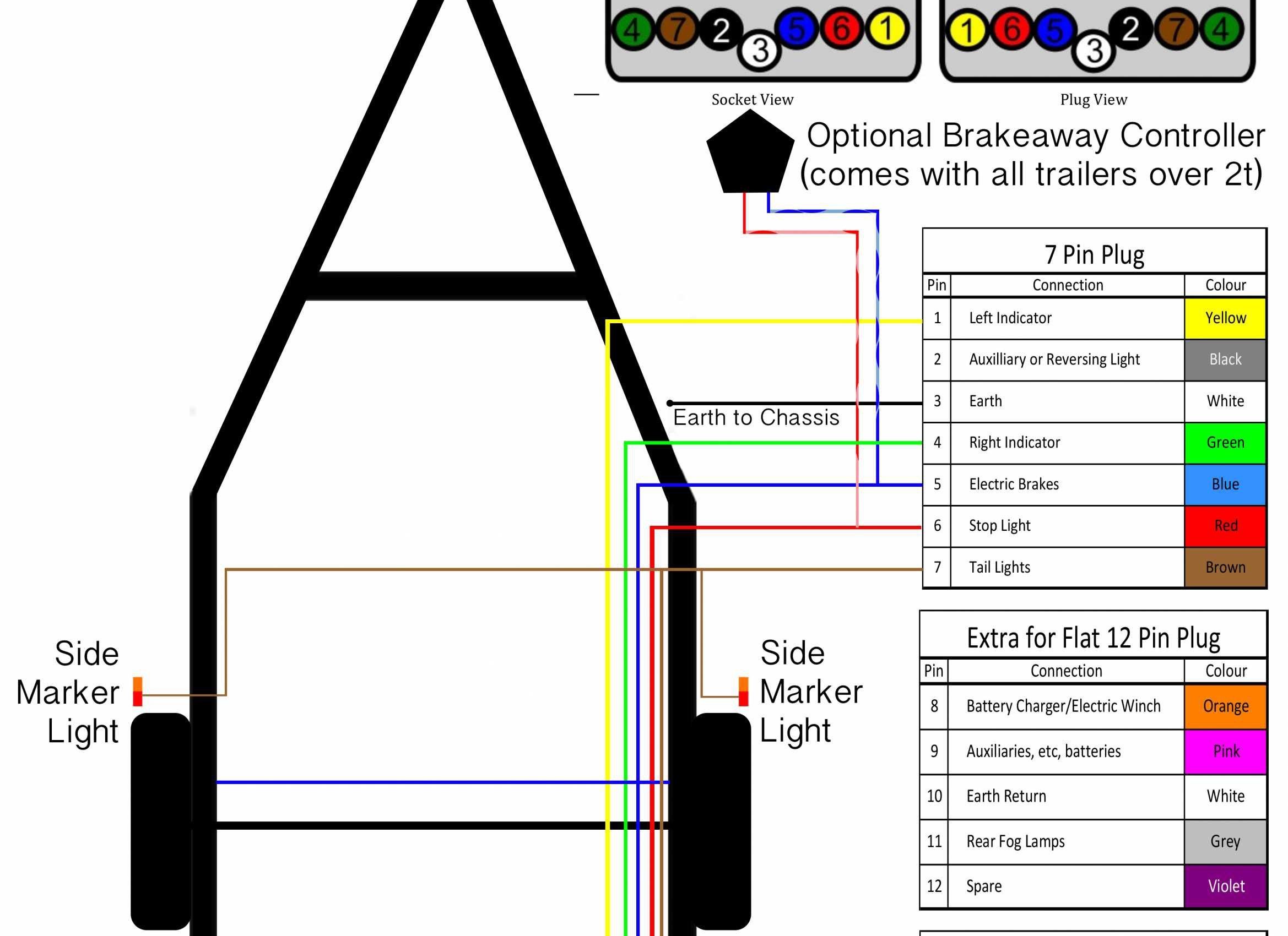
So, you're thinking about tackling the electric brake wiring on your trailer, huh? Good on ya! It's not rocket science, but it *is* something you need to get right for safety's sake. A clear understanding, starting with the wiring diagram, is crucial. We'll break down everything you need to know, from the purpose of the diagram to real-world troubleshooting.
Purpose of an Electric Brake Trailer Wiring Diagram
Think of the wiring diagram as the roadmap for your trailer's electrical system, specifically the braking system. It's far more than just a pretty picture of wires. Here’s why it’s indispensable:
- Repair and Maintenance: The diagram helps you quickly identify and trace circuits when something goes wrong. Let's say your trailer brakes aren't engaging. The diagram will guide you in testing continuity, voltage, and component functionality without randomly poking around and hoping for the best.
- Modification and Upgrades: Planning to add auxiliary lights, a battery charging system, or even upgrade your brake controller? The diagram is essential for ensuring compatibility and proper integration with the existing braking circuits.
- Learning and Understanding: Even if you're not actively working on the wiring, studying the diagram provides a solid understanding of how electric trailer brakes function, which, in turn, empowers you to diagnose issues more effectively.
- Safety: The most important reason of all. Incorrect wiring can lead to brake failure, electrical fires, and other hazardous situations. Following the diagram mitigates these risks.
Key Specs and Main Parts
Before diving into the diagram, let's review the key components you'll encounter:
- Tow Vehicle Connector (typically 7-way): This is where your trailer connects to your tow vehicle. It carries power for brakes, lights, turn signals, and often, a battery charging circuit. The standard 7-way RV blade connector is the most common.
- Electric Brake Controller: Located in the tow vehicle, it sends a variable voltage signal to the trailer brakes based on the vehicle's deceleration. Different types exist, including proportional and time-delayed controllers. Understanding your controller type is vital.
- Breakaway Switch: A critical safety device. In case of trailer separation from the tow vehicle, the breakaway switch activates the trailer brakes, bringing it to a halt. It's connected to the trailer battery and a dedicated brake circuit.
- Trailer Battery (if equipped): Provides power to the breakaway switch and may also support interior lights or other accessories.
- Junction Box: A central point where all the trailer wiring converges. It helps organize and protect the connections.
- Electric Brake Assemblies: Located inside each wheel hub, these assemblies convert electrical energy into mechanical braking force. They consist of electromagnets, brake shoes, and drums (or rotors in some cases).
- Wiring Harness: The bundle of wires connecting all the components. Use appropriate gauge (thickness) wire for each circuit. Undersized wire can overheat and cause voltage drop, hindering brake performance.
Symbols – Decoding the Diagram
Wiring diagrams use standard symbols to represent components and wiring. Here's a breakdown of common symbols:
- Lines: Solid lines indicate wires. Dashed lines often represent chassis ground connections. The thickness of the line doesn't usually indicate wire gauge.
- Colors: Each wire is typically assigned a color code (e.g., blue for brake signal, white for ground). These colors are critical for identification and troubleshooting. Common colors include:
- White: Ground
- Blue: Electric Brake Signal
- Black: 12V Power (Battery Charge)
- Brown: Right Turn/Brake
- Yellow: Left Turn/Brake
- Green: Tail Lights
- Red: Auxiliary (often used for breakaway switch)
- Circles/Rectangles with Letters: Represent components. For example, "BC" might stand for Brake Controller, "BS" for Breakaway Switch, and "JB" for Junction Box.
- Ground Symbol: A series of descending horizontal lines, indicating a connection to the chassis ground.
- Numbers/Letters on Wires: These often represent circuit identifiers or pin numbers on connectors, aiding in tracing and testing.
It's absolutely essential to have the correct wiring diagram for your specific trailer model and year. Generic diagrams can be helpful for understanding general principles, but they won't account for variations in wiring configurations. A quality diagram will include wire colors, component locations, and circuit numbers.
How It Works: The Brake Circuit in Action
Let’s trace the path of the brake signal, starting at the tow vehicle:
- When you apply the brakes in your tow vehicle, the brake controller senses the deceleration.
- The brake controller sends a variable voltage signal (usually 0-12V DC) through the blue wire in the tow vehicle connector. The amount of voltage is proportional to the braking force – harder braking means more voltage.
- This signal travels through the blue wire in the trailer wiring harness to the electric brake assemblies at each wheel.
- Inside the brake assembly, the voltage energizes an electromagnet. The stronger the voltage, the stronger the magnetic field.
- The electromagnet attracts an armature lever, which in turn applies pressure to the brake shoes.
- The brake shoes press against the rotating drum (or rotor), creating friction and slowing the trailer's wheels.
- When you release the brakes, the voltage to the electromagnets is cut off, the armature lever retracts, and the brake shoes release.
- The breakaway switch is connected directly to the trailer battery (if equipped) and the brake circuit. If the trailer becomes detached, the breakaway switch pin is pulled out, completing the circuit and activating the trailer brakes.
The grounding is just as important. A solid ground connection ensures proper circuit completion. Typically, the white wire connects to the trailer frame at multiple points.
Real-World Use – Basic Troubleshooting Tips
Here are a few common problems and how the wiring diagram can help diagnose them:
- No Trailer Brakes: Use a multimeter to check for voltage at the blue wire in the trailer connector when the tow vehicle brakes are applied. If there's no voltage, the problem lies in the tow vehicle's brake controller or wiring. If voltage *is* present, trace the blue wire through the trailer wiring to the brake assemblies, checking for breaks, corrosion, or loose connections along the way.
- One Brake Not Working: Use the wiring diagram to identify the specific brake circuit. Check the wiring to that brake assembly for continuity and voltage. Test the resistance of the electromagnet within the brake assembly. An open circuit or excessively high resistance indicates a faulty electromagnet.
- Breakaway Switch Not Working: Test the breakaway switch by pulling the pin. The trailer brakes should engage. If they don't, check the wiring from the trailer battery to the breakaway switch and then to the brake circuit. Ensure the battery is fully charged.
- Dim Lights, Erratic Brake Function: This often points to a grounding issue. Inspect all ground connections for corrosion and ensure they are securely attached to clean, bare metal.
Safety First!
Working with electrical systems can be dangerous. Keep these points in mind:
- Disconnect the Battery: Whenever you're working on the trailer wiring, always disconnect the trailer battery to prevent accidental shorts and potential electrical shocks. If your trailer has no battery, disconnect the 7-way connector from the tow vehicle.
- Use Proper Tools: Use insulated tools designed for electrical work.
- Work in a Dry Environment: Never work on electrical systems in wet or damp conditions.
- Inspect Wiring Regularly: Check for frayed wires, cracked insulation, and corroded connections. Replace damaged wiring immediately.
- The Brake Controller: If you suspect issues with the brake controller in your tow vehicle, refer to the manufacturer's instructions for troubleshooting. Improperly adjusted or malfunctioning brake controllers are a frequent source of braking problems. This is a high-risk component, and should be handled with care and respect.
Understanding your electric brake trailer wiring diagram is the first step to keeping your trailer safe and functional. Don't hesitate to consult a qualified mechanic if you're uncomfortable with any aspect of the electrical system. Remember to always prioritize safety and double-check your work.
We have a detailed electric brake trailer wiring diagram file available for download. This diagram includes color-coded wiring and clear component labels to assist with your project.